 Zachary Murtishi
I went ahead and soldered the THT components of the boards. I left off the piezo as I didn't really have a use for it. Everything seems to work pretty well.
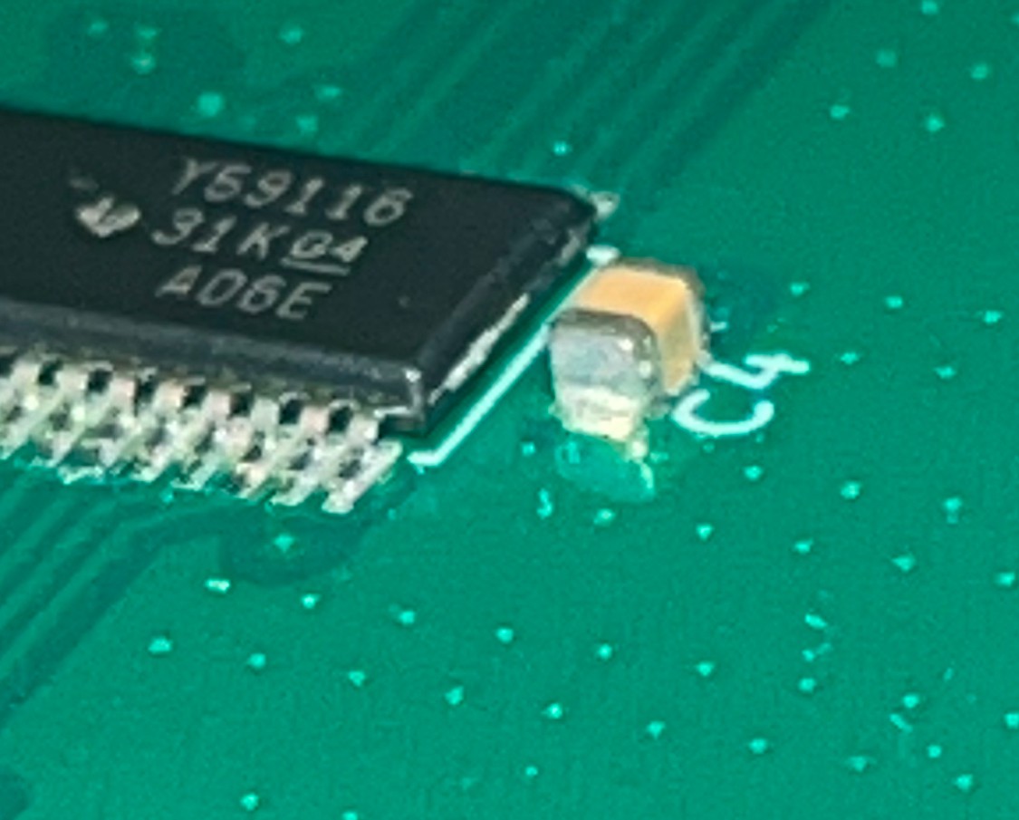
I noticed that an 0805 capacitor was accidentally specified in place of an 0603 part for the 100nf decoupling capacitors. It might not be compliant with IPC-A-610, but 0805s definitely can fit on an 0603 landing. I should probably update the BOM to reflect an 0603 part number later, but this is just a hobby project and I can verify that the part is soldered to the pad. Below is a picture of one of these 0805 100nf decoupling caps - this one is for the TLC59116 LED driver I'm using:
Before I work to port the game code to the ATtiny3224, I went and developed the interfaces required first:
- Got an I2C driver working. At first, I wrote my own TWI library and was able to talk to the TLC59116 after porting a library I wrote for the PIC18LF2420 to work with the ATtiny3224 TWI interface. I was able to implement 1-way I2C commands (write), but my attempts at a receive library were not as successful. I ended up consulting this ATtiny 1-series TWI library by bitbanging for help - I discovered I was being overly cautious with my implementation with all my checks of various TWI flags. I ended up importing their TWI library and tweaking some of the write functions to allow repeated writes with only the send byte function (it did not work out of the box so I added checks for both the receive/write complete flags as well as the bus state). I now have a 100 KHz I2C interface that is capable of communicating with both the TLC59116 LED driver and TCA9535 I/O expander.
- My code wasn't running how exactly I wanted to - for some reason, a for loop was not iterating over all 16 LEDs when I was trying to get them to light during debugging. I disabled avr-gcc's optimization after some extended debugging. Disabling compiler optimization seemed to do the trick; something about it was causing the last iteration of the for loop to not make it into the assembled code.
- Wrote a quick USART implementation to allow data exchange through the FT230X. Thankfully, USART wasn't very difficult to get going and I quickly wrote a library for simple I/O over the ATtiny3224 USART interface. As usual, I set it up for a 9600 baud, 8N1 serial scheme. I ended up setting up the receive complete interrupt to allow my debugging to not interfere with the main program loop - that is, I can send messages at any time during program execution and get a reply. Much better than my prototypes where I had blocking USART receive code in the while(1) loop. I'm glad to know that both my FT230X and level shifter implementation work in this application. I have to see what I want to do with this interface, but I'm likely just going to use it for debugging right now.
- I realized a little too late that the ATtiny3224 has a default divide-by-6 prescaler for the peripheral clock and wondered why my I2C bus was so slow compared to the value I thought I set (assuming a 20 MHz peripheral clock). Using the ccp_write_io function In the background, my test LED is being toggled every ~1s to test the system tick.provided in the cpufunc header, I was able to reconfigure the main prescaler to divide the main clock by 10 for a clean 2 MHz value to serve as my peripheral clock - sure it's slower than 3.3 MHz, but I like working with a clean number like 2 MHz more.
- I set up a simple 1 ms system tick with a Type B timer - the 2 MHz system clock is fed into a divide-by-16 prescaler and compared to a value of 125 to generate this 1ms tick. I will be using this for anything requiring a timing source going forward.
- I ended up removing the TCA9535 from the main program loop and moving it to an ISR triggered by the port interrupt vector - the TCA9535 has a pin that is pulled low upon change of its input port to indicate state changes to an MCU. Naturally, I tied this pin to an interrupt on PORTA. Instead of having this I/O expander periodically polled, it is only polled in the ISR upon detection of a falling edge on its assigned pin. It seems to work pretty well!
- I have a simple program loaded to test all interfaces/interrupts: press a button and the LED corresponding to it will toggle. I set up two buttons to change the brightness of the LEDs that are on.If I send a message to the board over an 8N1, 9600 baud USB COM port, it will reply with a character that is equal to the character that was sent plus one.
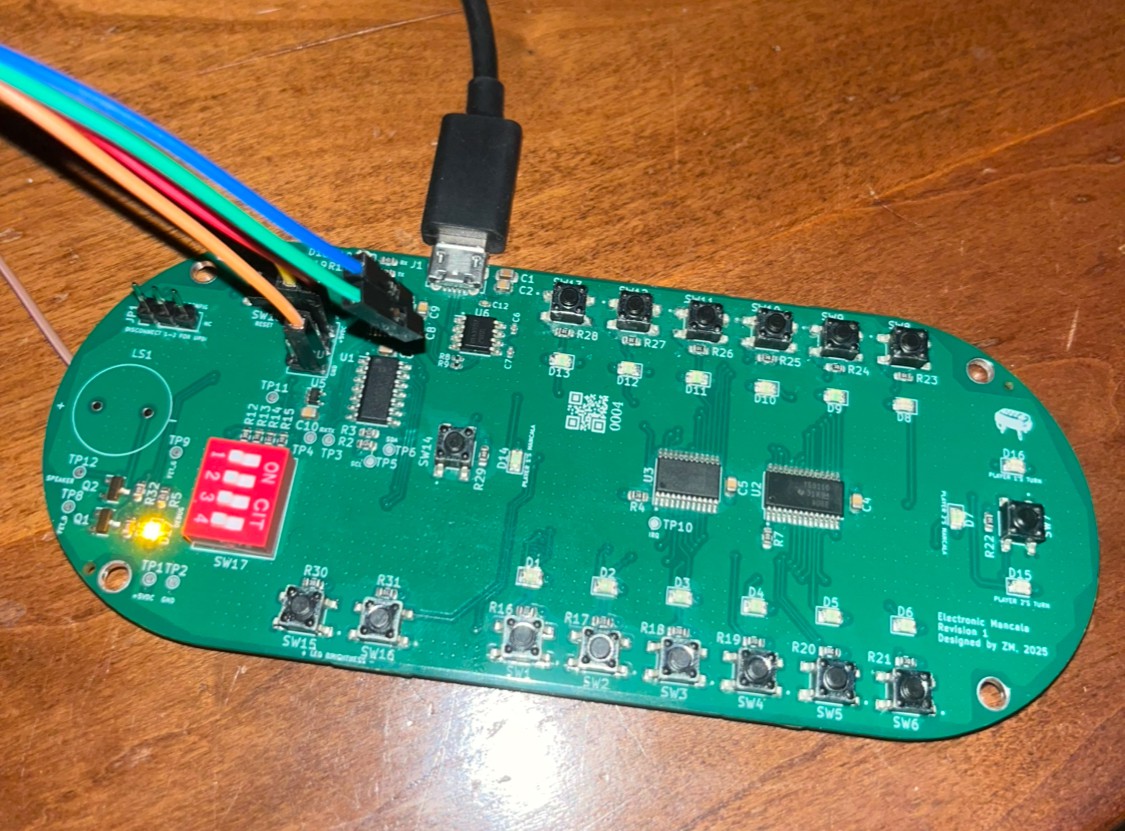
- Below is what the board looks like with my USB port (for USART testing) and PICkit 5 (debugging/programming attached. I really need to get a better USB dongle; I'm a Mac user and currently daisy-chaining several USB dongles to be able to use two USB ports at once.
Discussions
Become a Hackaday.io Member
Create an account to leave a comment. Already have an account? Log In.