 borazslo
Wiring Up: https://hackaday.io/project/20202/log/54574
Current Firmware: https://drive.google.com/file/d/0B2V4ksjbnZGWRk1NYkk2ek5IMlU/view?usp=sharing
NodeMCU with RFID reader, SD card logger, and OLED screen
Already have an account? Log in.
To make the experience fit your profile, pick a username and tell us what interests you.
Wiring Up: https://hackaday.io/project/20202/log/54574
Current Firmware: https://drive.google.com/file/d/0B2V4ksjbnZGWRk1NYkk2ek5IMlU/view?usp=sharing
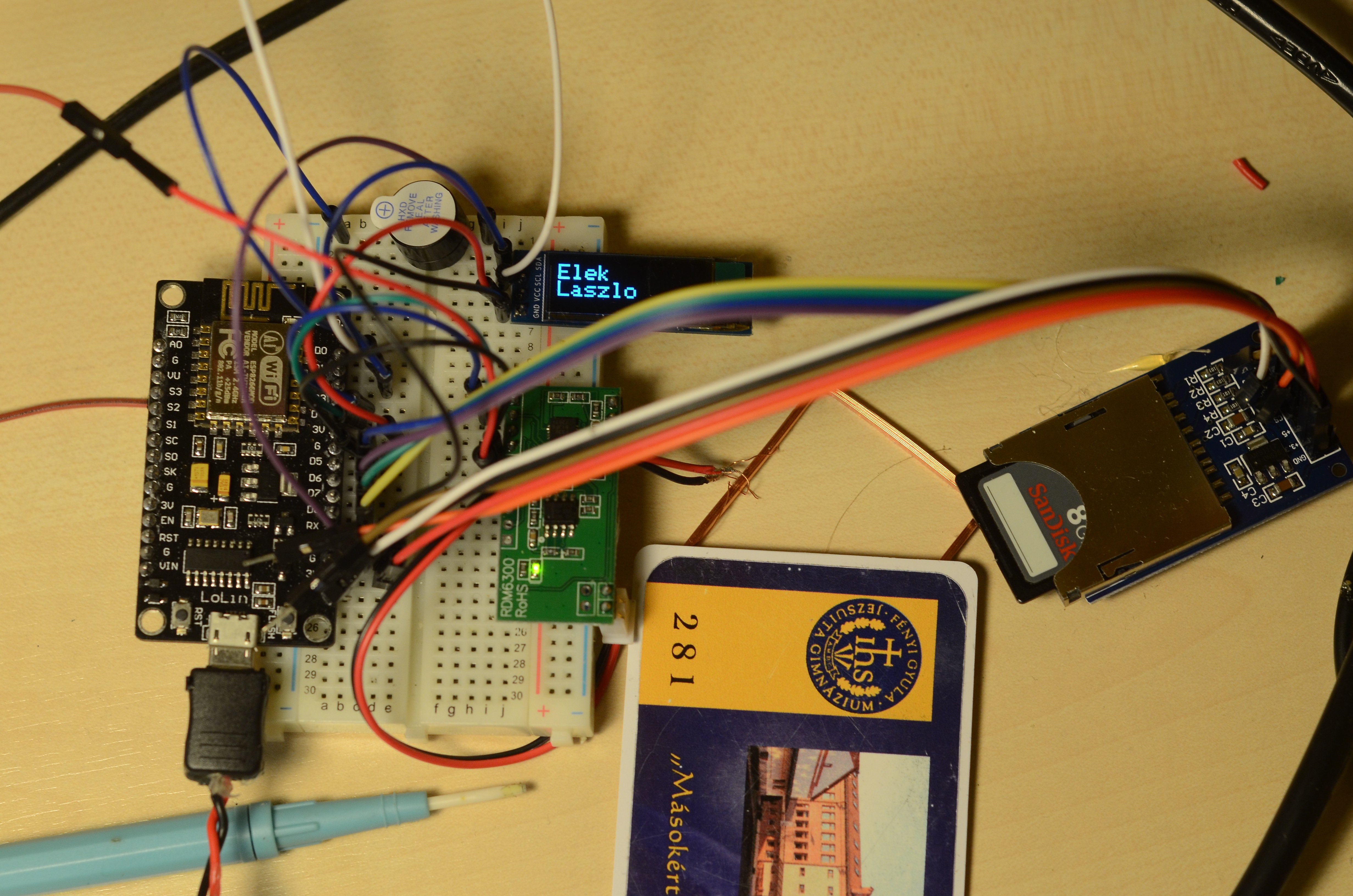
125Khz RFID module - NodeMCU: softwareSerial communication
+5V DC should be detached during firmware upload, because NodeMCU D3 is used also for FLASH.
SD Card SLOT - NodeMCU: SPI communication
128x32 OLED Display - NodeMCU: I2C communication
Buzzer - NodeMCU
NodeMCU D0 is used during flash of new firmware, so the buzzer needs to be disconnected during firmware update.
Please give me suggestions how to optimize these connections. How can I use for example A0, S3, S2, S1, SC, S0, SK, EN pins of NodeMCU?

 Pete Prodoehl
 YH-workshop
 bobricius
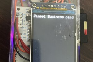
Hello, the project is excellent. It works very well. I tried all the details. But I have a problem. How can I change the time difference (utc+3) according to the country I live in. Thank you