Close
0%
0%

HP 110 Plus Lithium Battery Pack

Vintage computer enthusiasts, here is a lithium-ion battery pack for the venerable HP 110 Plus (HP 45711). Enjoy!

Public Chat
Similar projects worth following
0 followers
I have this HP-110Plus (HP45711) which uses a very old tech sealed lead-acid (SLA) battery.

Those batteries are heavy, hard to find in this specific dimension, and need constant baby-sitting and recharging to be kept alive.

Why not bring your favourite laptop (I am sure) to the 21st century and have a lithium battery (that can also catch fire without warning) instead?

On top of that, you can now ditch that old 8V AC HP82059B transformer (as it is falling apart anyway) and use USB-C power delivery instead!

What's not to like?

What you need

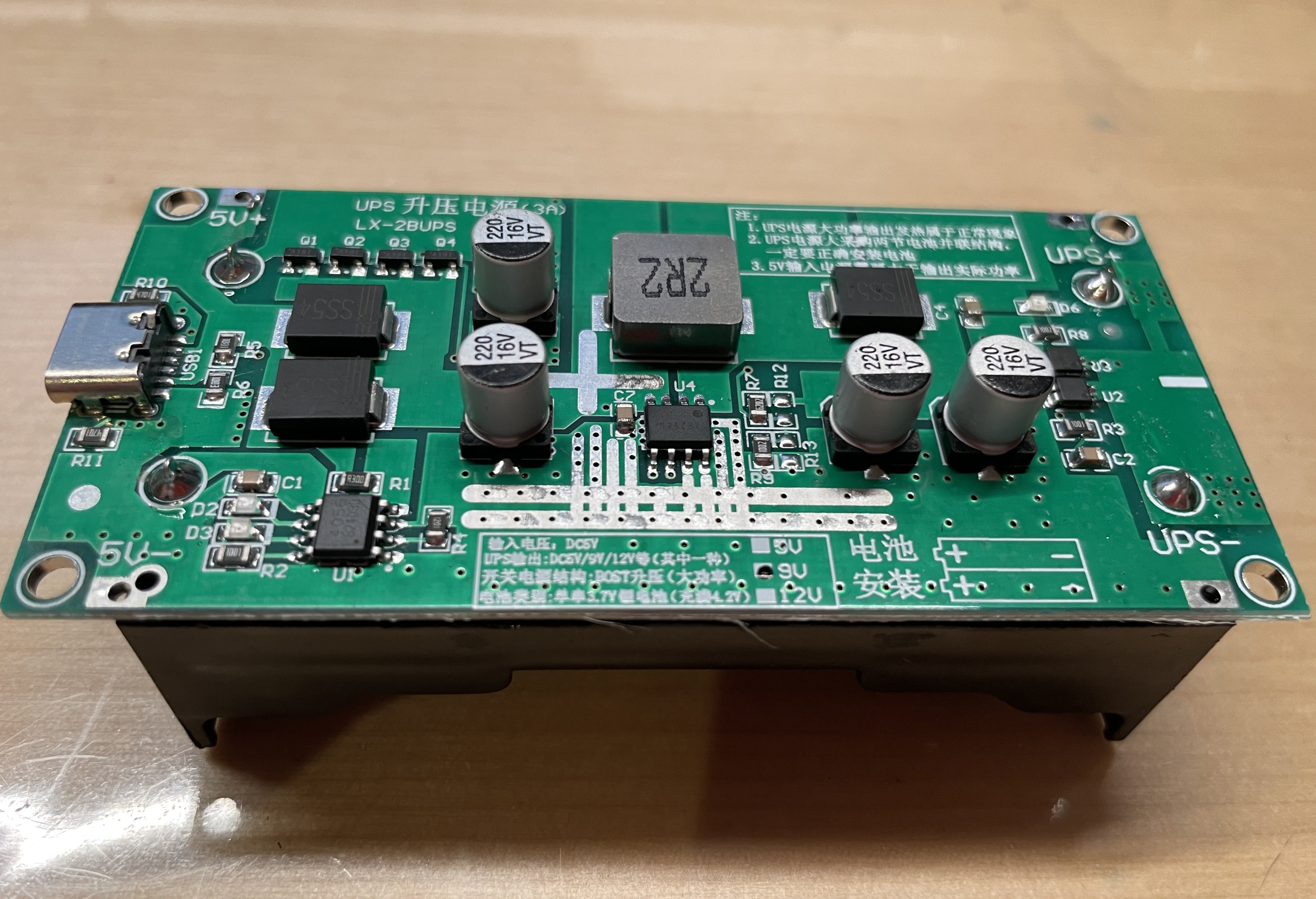
The battery pack is all based on one of those two-cell UPS that you can find for cheap on AliExpress. Only, because 6V output is not offered, we will have to do a little desoldering and soldering to fix that issue. I picked the 9V USB-C version as a base.

Follow the instructions...

  • 1
    What you need

    The battery pack is all based on one of those two-cell UPS that you can find for cheap on AliExpress. Only, because 6V output is not offered, we will have to do a little desoldering and soldering to fix that issue. I picked the 9V USB-C version as a base.

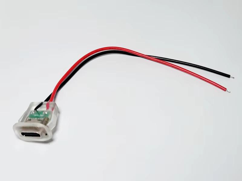
    Then, as the USB connector is not conveniently placed, we'll have to move it around, so I used those plugs. I like those because they support USB-C PD (power delivery), and light up when negotiation is complete and power is available. It doesn't mean the battery charges, but it's better than nothing.

    Note that I am not endorsing any of these vendors. It just happens that I bought from them. 

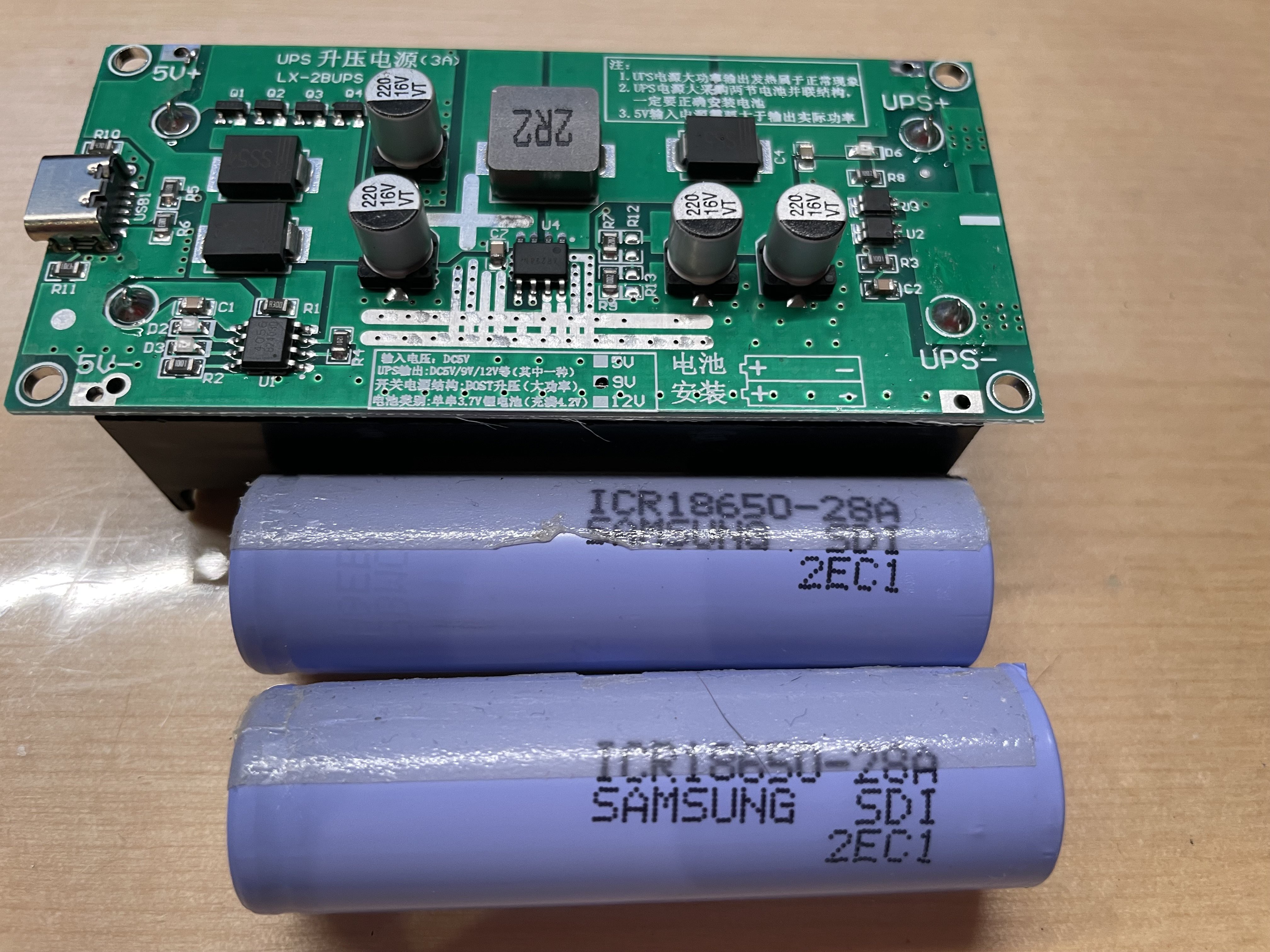
    Of course, we need to procure two 18650 li-ion cells. I wouldn't recommend AliExpress as there are a lot of fakes out there. I got good quality Samsung cells from a local computer recycler, for what it's worth. 

    We also need 1 x 0805 surface mount 39 kOhms resistor. Any other through hole resistor will do as long as you are able to solder the leads to the very tiny pads on the board. Amazon and AliExpress have resistor kits that include this value. If you buy a kit, make sure 39K is included as this is a rather infrequently used value. I got my resistor kit on eBay a few years ago. You could also get on Digi-Key or Mouser.

    For connection to the binding posts, we'll need two crimp ring connectors (#4 or M3) installed on about 2 inches of insulated wire for the negative side, and 5 inches for the positive side.

    To create the binding posts, we will need two M3 x 4mm threaded inserts and two M3 x 16mm pan head screws.

    To screw down the UPS PCB we will need four M3 x 8mm self tapping screws. Machine screws will work too, in a pinch.

  • 2
    Modifying the UPS board

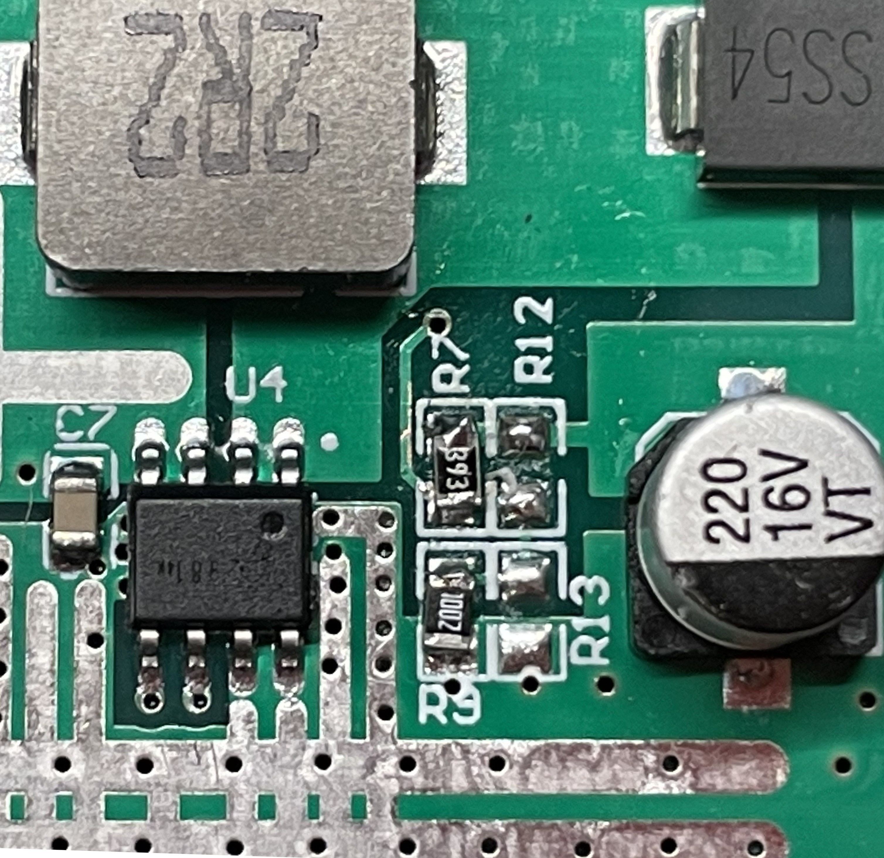
    Don't worry, it's easy. On this board, R7 determines the output voltage. For a 9V module, a 62K resistor is installed at the factory. We are going to change it to 39K to lower the output voltage to 6V to make our HP-110 Plus think it is powered by a lead-acid battery. 

    First of all, remove the cells if they are installed. Now is not a good time to create a short… Don't ask me how I know that.

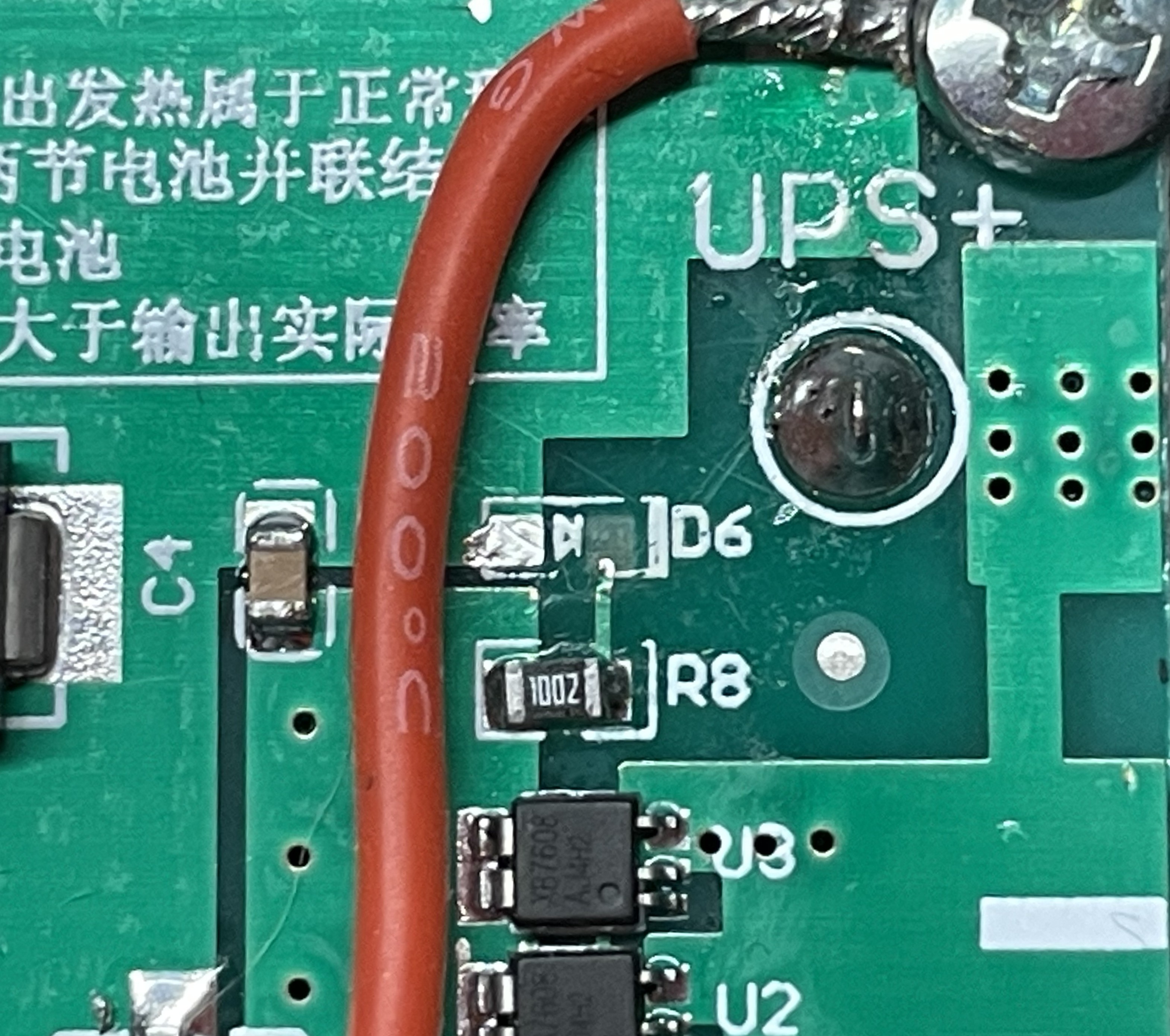
    For the sake of power efficiency, find D6 on the board (bottom left of the UPS+ terminal) and desolder using your favourite soldering iron (or here) and desoldering braid. You can also use a cheap hot air station such as this one and a pair of ceramic tweezers.
    Using the side of the soldering iron tip, we can simply heat up both pads from the side of the LED and slide it away from the pads. Flux helps spread the heat. Use the braid to clean up the pads. (I was a bit brutal with my temperature setting and manage to delaminate one of the pads).

    This orange LED is on whenever the UPS output is on. As the module is enclosed inside the computer and that LED will just burn away some of the energy stored in the battery for nothing, we'll just remove it. To whoever designed this: I'll be charitable and call that always-on LED on a battery powered device an “interesting” design decision. 5mA lost forever for nothing…

    R7 resides just to the bottom right corner of the large grey square coil. Remove R7 (the tiny digits on it should read 6202). Then, using either solder paste and a hot air station or fine solder and an equally fine soldering iron tip, install the new 39K resistor (marked 393, 3902, or even 58C depending on the code used and how precise the value is) in its place.

    Clean up whatever flux is left after the battle using isopropyl alcohol. 

    Install the two cells and verify the voltage between UPS+ and UPS- is close to 6V with a voltmeter. My board gives exactly 6.0V but that's not in fact critical as a lead-acid battery will go from 6.6V fully charged down to 5.7V at 10% capacity. I am not sure where HP placed the cutoff point, but as long as the voltage is hovering around 6V, we should be fine.

  • 3
    Printing

    There are two plates in the print profile, and each plate uses a different colour.

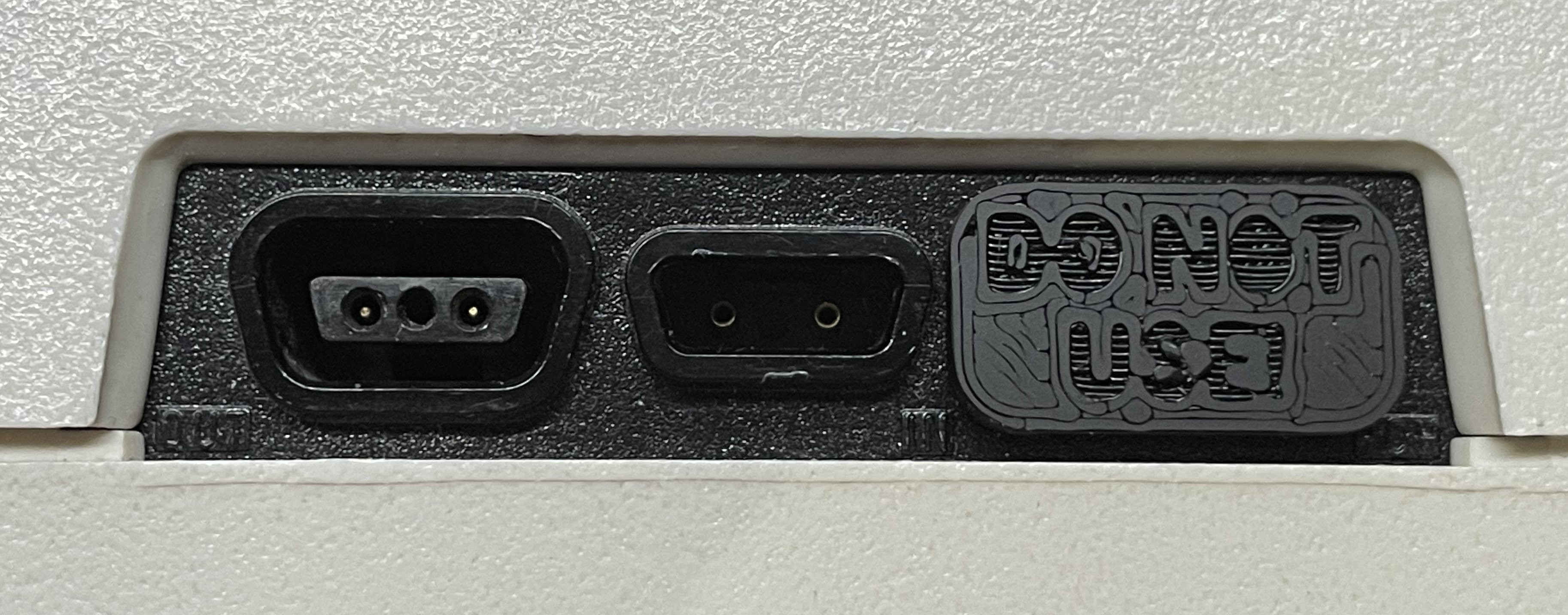
    The first plate contains the bracket, a plate, and a little plug. You can print it in any colour you like as long as it is black… Joke aside, as the bracket and the plate are inside the computer, the colour is unimportant unless you really care about the colour of the plug, if you think you will be using the plug. That plug is meant to be installed on the charging port of the computer to prevent you from trying to recharge the battery pack using the old 8V AC charger. Nothing should happen if you plug a charger as the UPS output is supposed to be protected according to the sketchy description I managed to find, but I haven't actually tried. You may want to be cautious with a 40+ year old computer though…

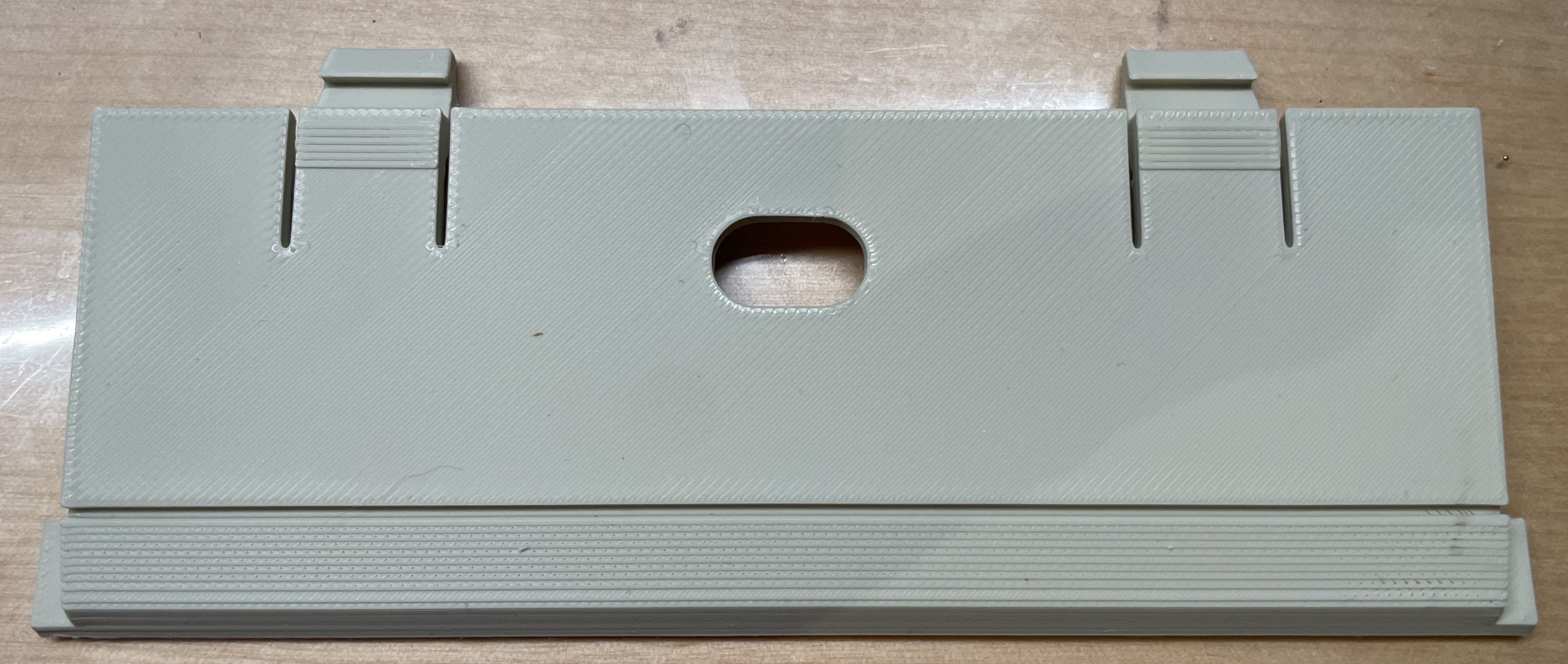
    The second plate contains the cover. eSun used to make a light khaki matte PLA filament that would almost (but not quite) match the colour of the case, but this hue is not available anymore. The hunt for the perfect vintage beige continues! You may want to try this one as a replacement. Bambulab also has beige filament, but the colour is far off. After printing, be sure to remove all the support material. As I used normal supports, it should be relatively easy to remove (tree supports don't work well in this use case).

View all 5 instructions

Enjoy this project?

Share

Discussions

Similar Projects

Does this project spark your interest?

Become a member to follow this project and never miss any updates