 CiferTech
The motivation behind RF-Clown was to create a tool that could serve as an example of open-source collaboration. Many similar projects remain closed, limiting their use to a select few. With RF-Clown, all resources—from code to PCB designs—are freely available on GitHub, ensuring transparency and accessibility.
This blog post will guide you through the RF-Clown project, detailing its features, design, and implementation. Additionally, we'll discuss how to build it using a breadboard and explore its potential applications.
🛠️ Features
RF-Clown is a compact yet powerful BLE and Classic Bluetooth jammer with the following features:
- Multi-Mode Operation: Supports jamming for BLE, Classic Bluetooth, or both simultaneously.
- Compact Design: Optimized PCB layout for portability and ease of assembly.
- NeoPixel LED Indicator: Displays the current operating mode for easy identification.
- Power Management: Includes a TP4056 for charging and an LF33 voltage regulator for stable operation.
- Open Source: Full access to code, schematics, and PCB designs.
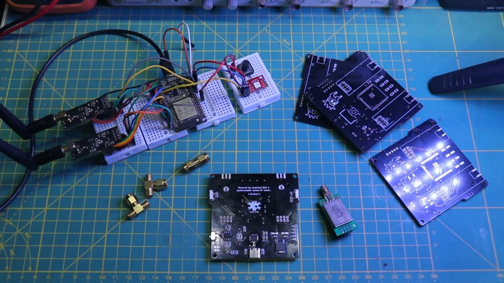
🎨 Building the Breadboard Version
For enthusiasts who prefer experimenting with the hardware before committing to soldering or PCB fabrication, RF-Clown can be assembled on a breadboard. This approach allows you to test and modify the project as needed.
Required Components
| Component | Quantity | Description |
|---|---|---|
| ESP32 | 1 | Main microcontroller |
| NRF24L01 | 2 | Wireless transceivers |
| NeoPixel LED | 1 | RGB LED for mode indication |
| CP2102 USB to Serial | 1 | For programming the ESP32 |
| TP4056 | 1 | Lithium battery charger |
| LF33 Voltage Regulator | 1 | 3.3V output regulator |
| Micro Switch | 1 | Mode selection |
| Resistors, Wires | - | Miscellaneous |
🔌 Breadboard Wiring Guide
Below are the connections for the breadboard version of RF-Clown:
- RF-Clown Breadboard Version Pin Connections
| Component | Pin | ESP32 Pin (GPIO) |
|---|---|---|
| NeoPixel | Data | GPIO 4 |
| Button | Signal | GPIO 33 |
| NRF24L01 (VSPI) | CS | GPIO 15 |
| NRF24L01 (VSPI) | CE | GPIO 5 |
| NRF24L01 (HSPI) | CS | GPIO 22 |
| NRF24L01 (HSPI) | CE | GPIO 21 |
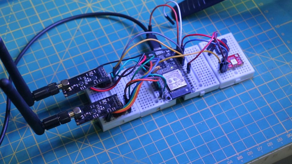
Assembly Steps
- Connect the ESP32 to the breadboard.
- Attach the NRF24L01 modules to the respective SPI interfaces (VSPI and HSPI).
- Connect the NeoPixel LED to GPIO 4.
- Add the mode button to GPIO 33.
- Wire the TP4056 and LF33 for power management.
- Double-check all connections against the table above.
- Program the ESP32 using the CP2102 module.
📜 Writing the Code
The heart of RF-Clown lies in its firmware. The code is structured to allow seamless switching between BLE, Classic Bluetooth, and combined modes. Here’s an overview of the key functions:
Mode Switching
RF-Clown uses a button connected to GPIO 33 to switch between modes. A NeoPixel LED provides visual feedback:
- Blue: BLE mode.
- Green: Classic Bluetooth mode.
- Red: Combined mode.
SPI Configuration
The ESP32’s VSPI and HSPI interfaces control two NRF24L01 modules simultaneously. This setup allows efficient hopping across multiple frequencies.
void configureRadio(RF24 &radio, int channel, SPIClass *spi) {    if (radio.begin(spi)) {        radio.setAutoAck(false);        radio.stopListening();        radio.setPALevel(RF24_PA_MAX, true);        radio.startConstCarrier(RF24_PA_HIGH, channel);    }
}
Jamming Functions
Each mode employs different channel sets to disrupt communication:
- BLE Channels: 2, 26, 80
- Classic Bluetooth Channels: 32, 34, 46, 48, 50, 52, etc.
void jamBLE() {    int randomIndex = random(0, sizeof(ble_channels) / sizeof(ble_channels[0]));    radioVSPI.setChannel(ble_channels[randomIndex]);
}
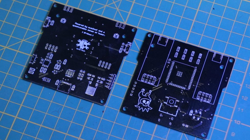
🚀 PCB Design
A custom PCB was designed to make RF-Clown portable and robust. The PCB integrates all components, including the ESP32, NRF24L01 modules, NeoPixel LED, and power management circuitry.
Key Features of the PCB
- Compact layout for portability.
- Dedicated headers for NRF24L01 modules.
- Integrated CP2102 for programming.
- Power management with TP4056 and LF33.
Code & PCB
If you’re interested in building this project, the code and schematic...
Read more »