 colton.baldridge
Picking up where I left off in the last project log, I began working with the idea that I could use PCB coils to generate a magnetic field that could be used to flip a dot. I already had some experience with PCB coils from my OS3M Mouse project, so I knew the theory was sound and that my fab house of choice (JLC) could create the hardware.
(generic PCB coil image, not mine)
So I set to brainstorming some ideas. How could I get the magnetic field from the coils to the magnetic dot? How many coil turns do I need? How much current do I need? How many layers should the PCB be? As I thought more, I came to the realization that I needed to buy down some risk. I needed to create a dev board, before jumping into making a full array. So I set to work: I needed a board that would tell me the following:
- What is the minimum number of turns I can get away with (determines coil size and thus flip dot pixel "pitch")
- How many layers do I need (strong driver of PCB cost)
- How much current will I need to flip the dot (determines heat load on the coil, drives framerate of the display, also informs driver selection)
- What does the mechanical structure need to look like to transfer magnetic flux from the coils to the flippable dot (general project risk)
- Can this even work at all?
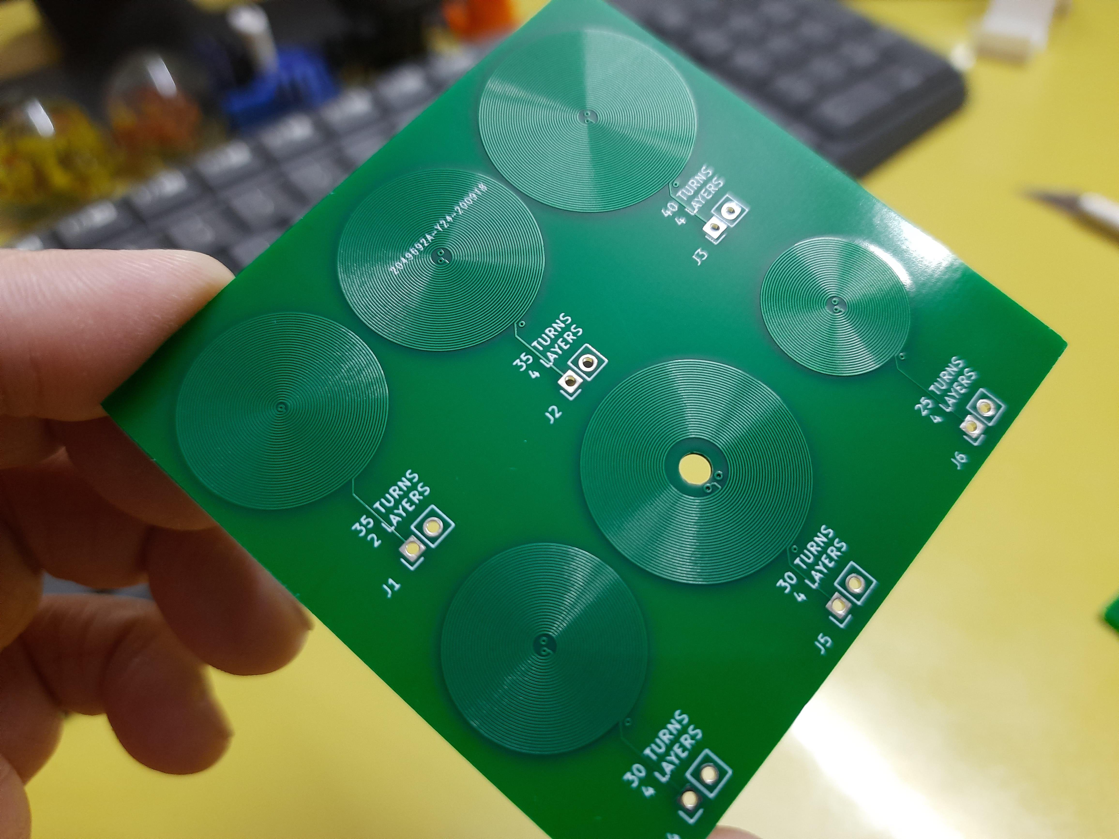
So I set to work designing a board that would allow me to answer these questions and more. I started by breaking out my trusty PCB coil designer script, but it needed a bit of modification. I added features to support more than 2 layers, a center drill hole, and added some features to make breaking out the layers a bit simpler. (commit coming soon). I then decided (somewhat arbitrarily) that I would like to test 10, 20, 30, and 50 turns, as those made reasonably sized coils at JLC's minimum recommended trace width and spacing (0.15mm). I also decided on 16AWG galvanized steel wire to be my "core" material that would transfer my flux to the magnet in the dot. I did this because steel (low carbon) has decently high permeability, and it was cheaply available at my local Home Depot. I want this to be cheaply and readily available to anyone who wants to build one, which means custom ferrite cores (like what is used by real flip dots, I believe) are off the table. I then began the process of mechanical and electrical codesign. I laid out an outline of a board in my CAD suite, where each coil was a protrusion on a side of the pentagon, and one last side was to be used as the interface.
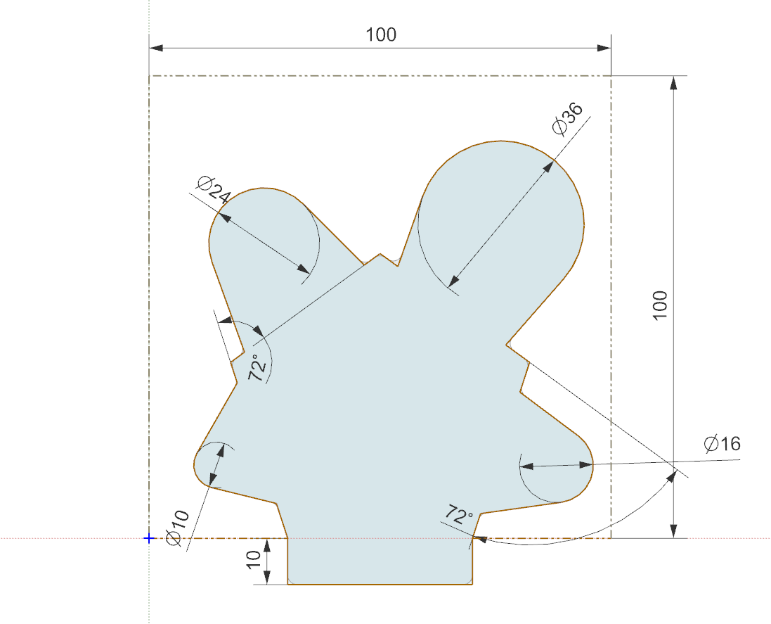
The reasoning for this shape was so that I could place any 2 coils side by side, and then put metal in a ‘U’ shape between them. That would allow me to build flipdots of varying coil size without much modification of the flipdot’s mechanicals, and all I would have to do is swap connections on the pin headers to the new coils.
I also wanted to try out some drivers for the dots, so I integrated 4 into each dev board. These drivers needed to be CHEAP, as I am gonna need hundreds of them. Thankfully, driving a PCB coil is basically the same as driving a little DC brushed motor. This means I can leverage the wide selection of VERY cheap DC motor drivers on LCSC. The one I chose was the TC8301, which has a datasheet almost entirely in Chinese, but thanks to Google translate, I was able to discern the key parameters:
- VCC_max = 7.2V
- P_max = 0.96W
- RDS_on = 1.6ohms
- I_max = 2.5A (no time limit given)
- I_cont = 1.5A
This little chip is only THREE CENTS so it should be a perfect candidate for use in the big array. Down the road, to further save on cost and board space, I’d like to multiplex the array so I only have to have drivers for each column/row rather than for each dot.
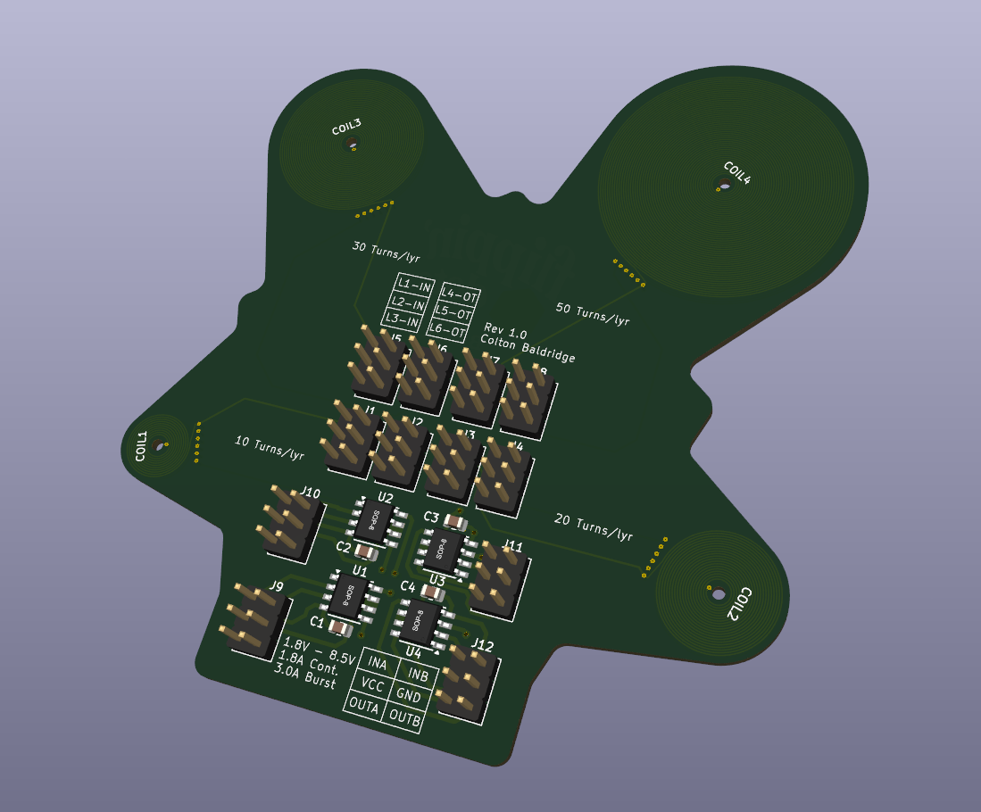
With all this in mind, I cracked open Kicad and designed it. I hadn't worked with Kicad in a while, so while I remember the fundamentals of PCB design, the mechanics of it were a bit clunky. I wanted to recommend this video to anyone else in my position. It covers all you really need to know in 13min, which is WAY less than many other videos out there. No fluff, just what you need to know. There weren't any real complex aspects to this board other than how I had to bring in the externally generated coils, and like magic, Kicad identified the arcs from the outline dxf, so it centered them perfectly. Here is how it turned out:
I somehow got onto the topic of my flip dots with my friends and asked them what they would put on the PCB. One of them had the wonderful idea of copying the Dippin' Dots logo, but make it into "Flippin' Dots". I thought this was hilarious, and I had recently heard that ChatGPT had announced a new image generation AI that was apparently super good. Turns out - it is. Here is what the result looked like, after a bit of masking to get the art on the layers I wanted:

I was incredibly impressed with the quality, and highly recommend this for silk art in the future.
And with that, I sent the board off to JLC for both PCB fabrication and assembly. Stay tuned to see how the board turns out and if this project has a future!
Discussions
Become a Hackaday.io Member
Create an account to leave a comment. Already have an account? Log In.