CONTEXT
Being able to pass a Power Electronics laboratory class gave me extra confidence in building this project -- I have been interested in that field after all -- so I thought maybe I could delve into that again. So I decided to build a Power Bank, with the main difference from a regular Power Bank being that it remains on top of your desk, workbench, or table. That sounds more like a charging station, doesn't it? And so, I decided to call this project the PowerDock v1.0.
Note: This project is the first version, and as such is open to improvements!
DESIGN AND CONCEPT
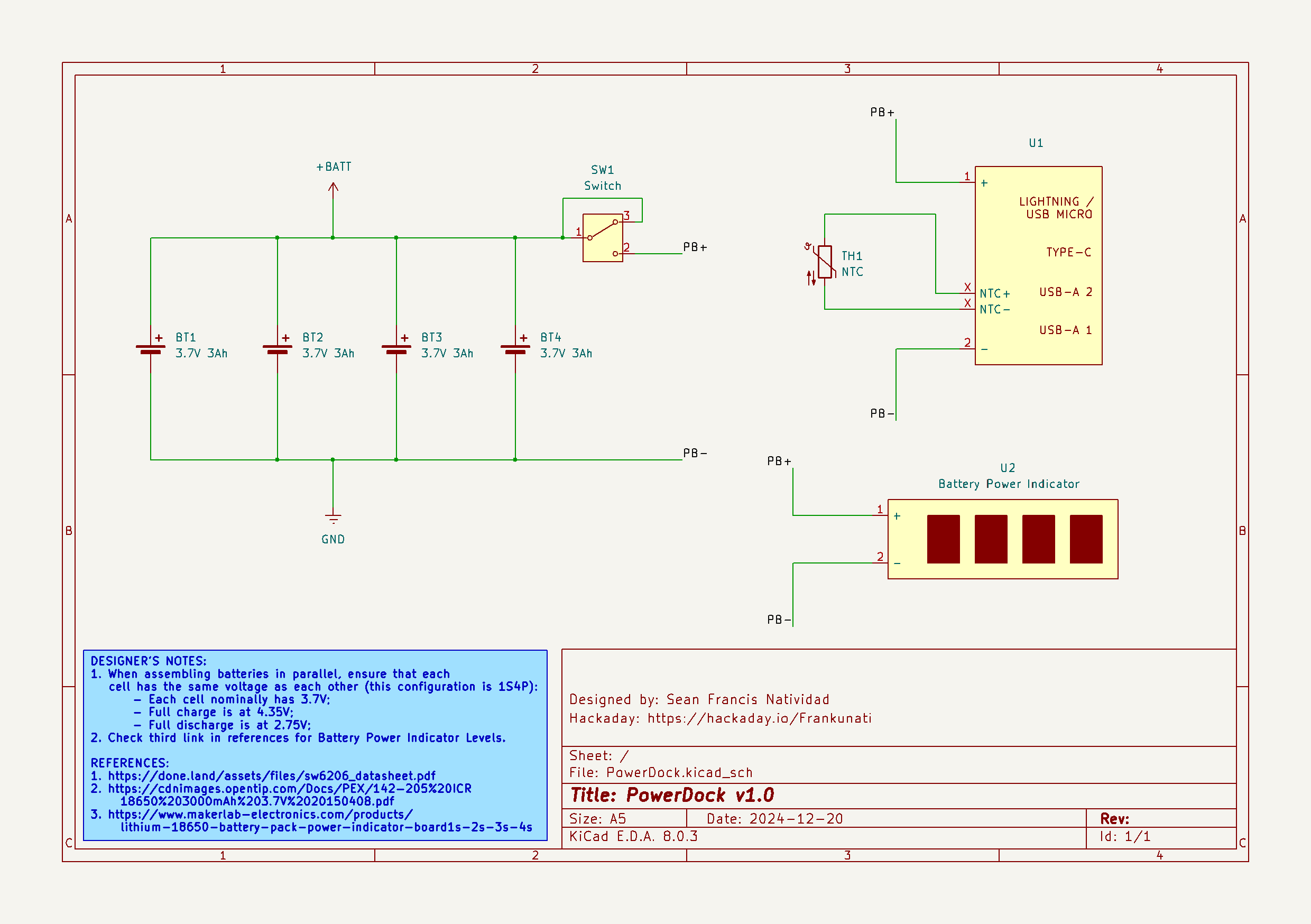
The PowerDock's Schematic
In its simplest form, the PowerDock is a Power Bank, whose only difference being it is meant to be placed on top of a table, desk, or workbench. As such, the "design" part of the project lies mainly on the battery pack's specifications. The SW6206 22.5W Power Bank Module's datasheet, it supports 4.2V, 4.35V, 4.4V, and 4.5V batteries. As such, a 3.7V Li-Ion Battery would suffice. With the goal of making a 1S4P battery pack, I ended up with the following specifications:
Battery Pack Specs:
1.) Voltage: 3.7V Nominal, 4.35V Full, 2.75V Discharged
2.) Capacity: 12Ah
3.) Battery Configuration: 1S4P
4.) Maximum Energy: 44.4 Wh
5.) Maximum Discharge Rate: 17.6 A
[More specs to be added!]
PROCESS
And now, to the process! Down below is the list of components you'll need to be able to assemble the PowerDock:
Parts/Components:
(4) PKCell ICR18650 3.7V 3000mAh Li-Ion Battery
(1) 4-Cell 18650 Battery Cell Holder
(1) Slide Switch
(1) Battery Power Indicator
(1) SW6206 22.5W Power Bank Module w/ built-in NTC Thermistor
(1) DC Wattmeter with USB Output for Power Output Testing
With the components gathered, I then proceeded to assemble the electronics. I began by setting the battery cells into the holder in parallel configuration -- not forgetting that the voltage in each cell must be the same (I measured each cell at 3.7V). My particular cell holder has pins that could be soldered together depending on whether or not you'd like the cells to be fixed in either series or parallel configuration. I also ensured that the built-in NTC Thermistor is in direct contact with one of the battery cells. For extra safety, I wrapped the battery pack in electrical tape. The initial setup looked like so:
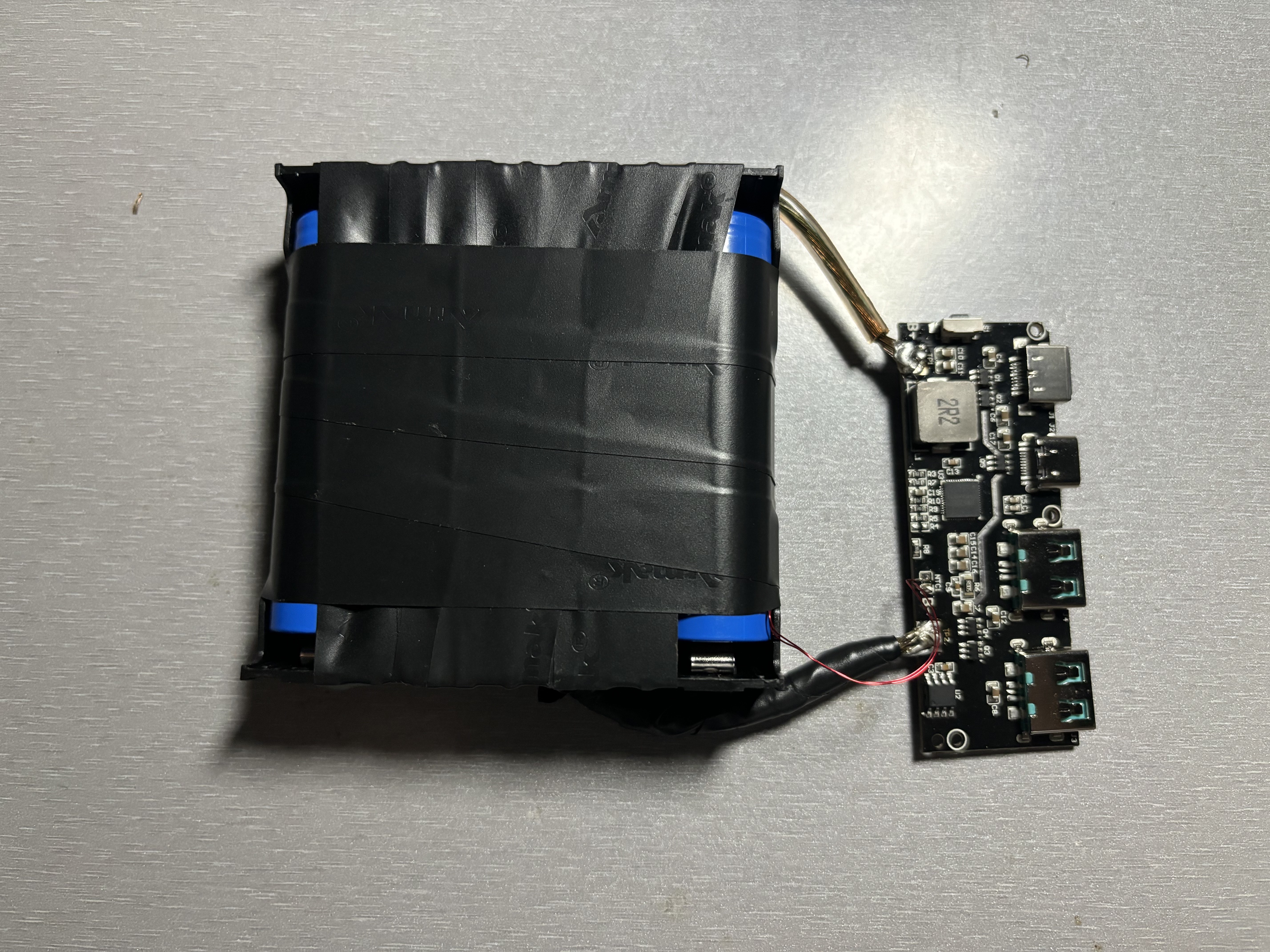 Initial Battery Pack and Power Bank Module assembly
With the initial assembly put together, my first thought was that, "I wanna see the thing light up!" (Light up as in... see actual LEDs turn on.. not see the thing burn..) So I plugged my type-c fast charger into an outlet and the other end to my Power Bank Module and indeed, it lit up. It's a relief to see that it works without any issues at all, AND for it to arrive in 3 days? Brilliant!

Two-Way Charge Test
After doing the two steps above, I then connected the Battery Power Indicator in parallel with the cells and the power terminals of the SW6206 Power Bank Module. As expected, it works. The indicator's levels change depending on the amount of voltage present in the battery pack. (See third reference in the REFERENCES section to see the corresponding number of bars to the voltage present in the cells.)
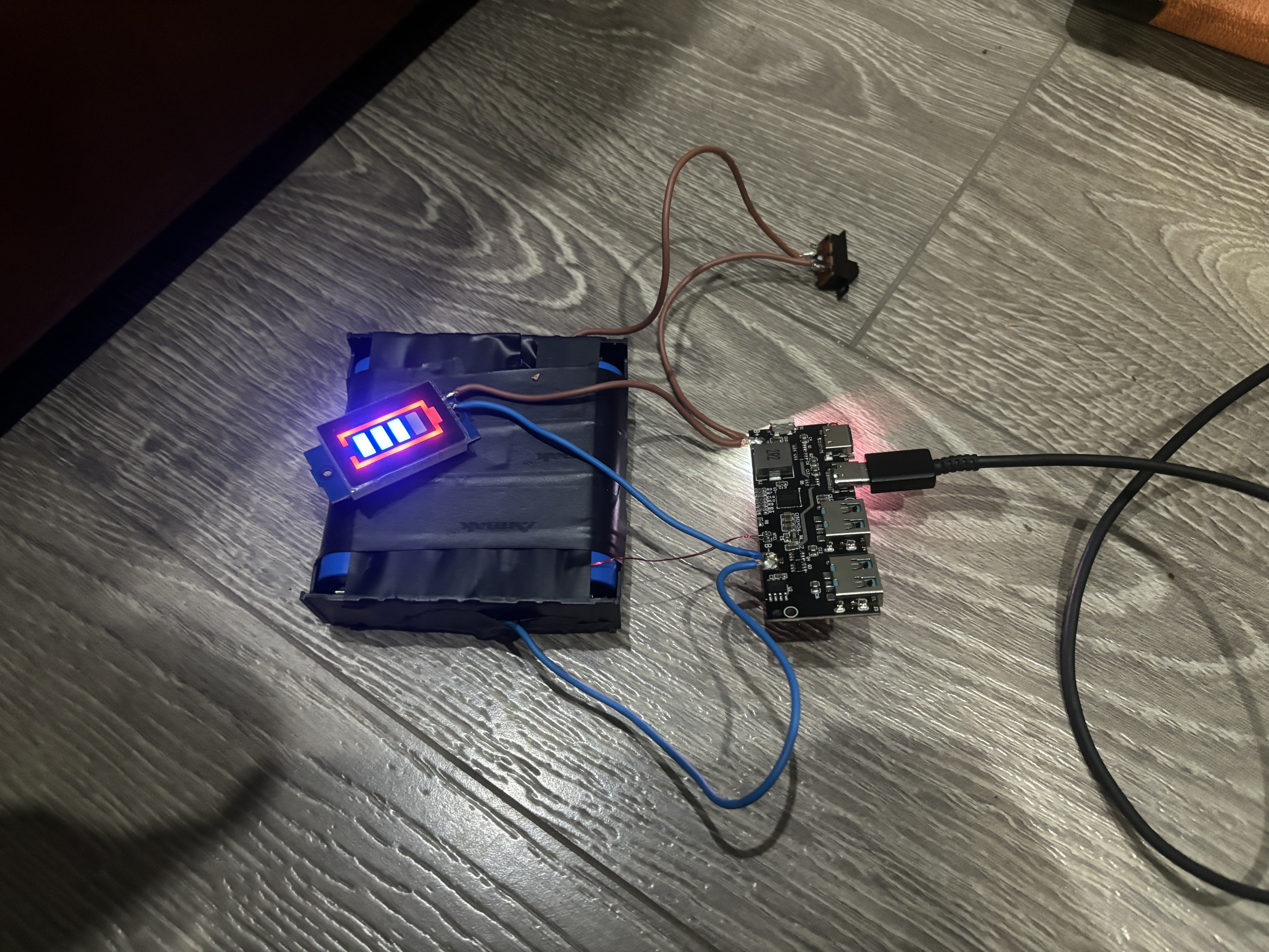
Assembly with the Battery Power Indicator
And now, with the electronics' completed, I proceeded to design a 3D-printed enclosure for the PowerDock. Attempting to maintain practicality while mixing in aesthetics, I designed i such that: 1.) each component that is supposed to be exposed is reachable; 2.) there is enough ventilation for the battery pack, and; 3.) there is appropriate branding for the device itself. I took the liberty of taking inspiration from Cyberpunk aesthetics as evident in the grills of the enclosure, and chose gray as the color for the enclosure.
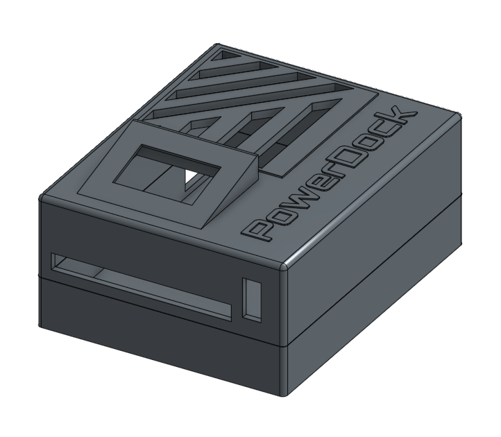
The 3D-Printed Enclosure, mildly inspired by Cyberpunk aesthetics
OUTPUT
 Frankunati
 Benchoff
 Enki
Enki
 Thijs Koppen
 Meta Unknown