 bru3s
bru3sOverview
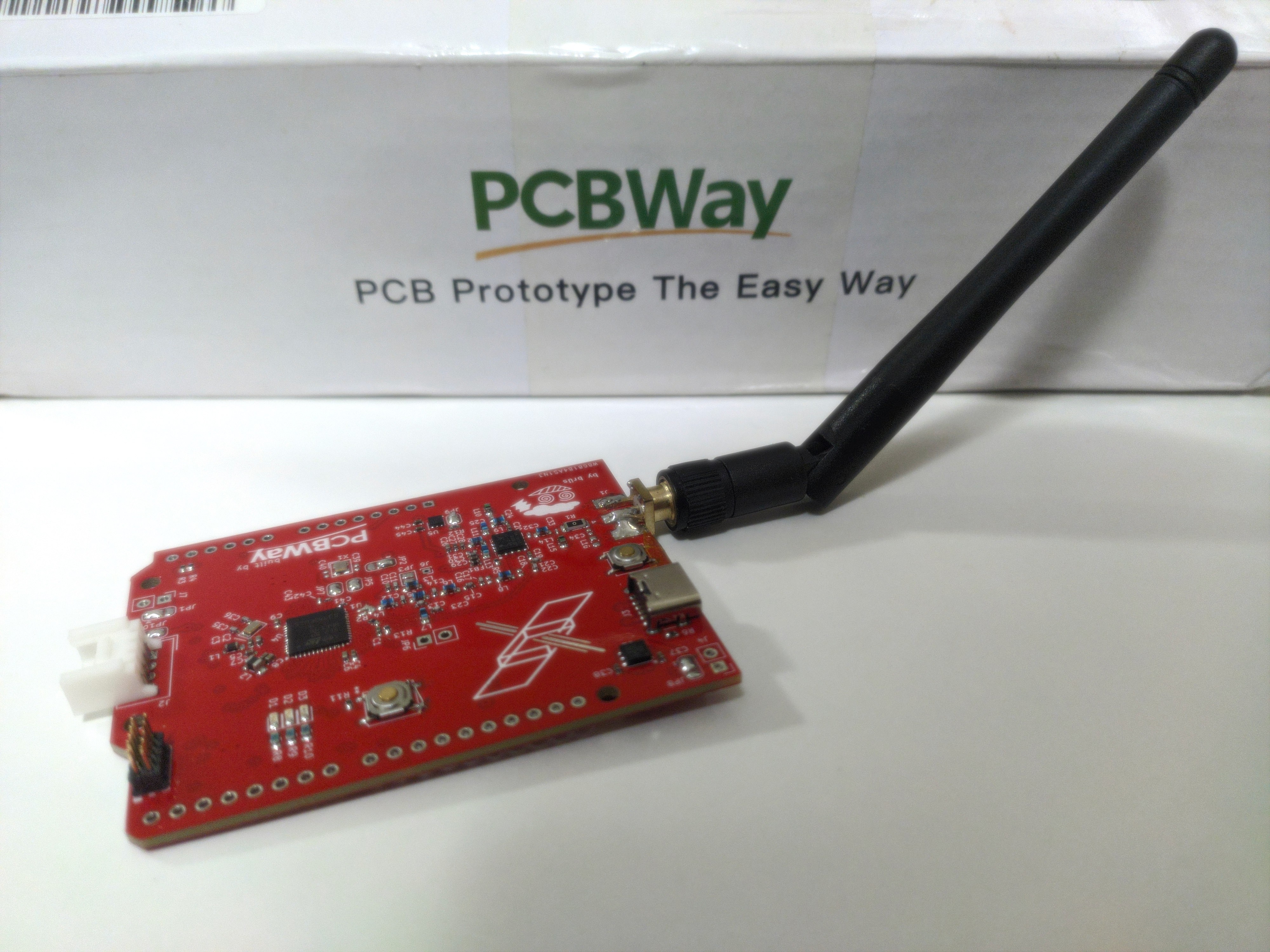
This board is based on an STM32WLE5 microcontroller from STMicroelectronics, which couples a Cortex-M4 MCU with an Semtech SX126x radio for LoRa communication (and other modulation schemes, as well). The transmission stage of the radio also sports a Skyworks power amplifier that allows this board to reach up to 30 dBm output power.
It is designed around the popular Arduino form factor for interchangeability with existing hardware. Currently the RF section is built to operate at the 169 MHz band for experimental reasons, however future revisions may move away from this frequency to 433 MHz and other bands.
The design is open, and this page was created to collect progress logs on FW development and HW revisions, which I aim to deliver in the near future.
Notice (here be dragons)
Before proceeding, I'd like to immediately point out an important notice for whomever is interested in replicating this project: only do so if you're in possession of the required HAM license to operate at higher power levels that this board can deliver, and that your local regulatory body allows to operate at this frequency with the indicate power.
I decline any responsibility due to third parties misusing hardware directly produced as a result of the provided design files or any derivative work thereof, including any illegal activities or violations of local laws, regulations, or guidelines related to HAM or radio frequency operation. It is your sole responsibility to ensure that your use of the hardware complies with all legal requirements and safety standards in your jurisdiction. Additionally, I am not liable for any damage, injury, or legal consequences that may arise from the use or misuse of this project.
Acknowledgments
Huge thanks to PCBWay for sponsoring this project. The board prototype was produced by them, who also took care of assembly and part procurement. They did an excellent job and were extremely thorough in their process, which made the whole PCB production a breeze. I would recommend anyone trying out PCB development (and not only PCBs!) to check their services out.
Motivation
During the last months at $CURRENT_JOB I've been involved several times with radio hardware solutions based on LoRa communication, which sparked my interest to keep experimenting outside of work-related activities.
One of the things I wanted the most was to try my hand at designing a PCB involving actual high("ish") RF frequencies necessary to operate radio communication, and since I already gained some experience in how LoRa works and what you can do with it, this project seemed like the natural candidate to do so.
I chose this MCU mostly because I'm pretty familiar with STM32 microcontrollers and since all LoRa ICs are (AFAIK) spun up on Semtech hardware I would have had to include an SX device in there anyway, which would have in turn required an additional MCU to drive it and make the board truly standalone. Though these micros from ST are kind of expensive the allowed me to simplify the design and keep everything in a simple package.
The addition of a boosted output stage, implemented via a dedicated power amplifier (and RF switch), is motivated by my desire to experiment with very long range communication via LoRa, which is in itself already a very good candidate due to his robustness and capability. Early trials with commercial LoRa hardware showed very promising results, which I however felt were a bit crippled by the maximum power output that most commercial IC can reach, which is usually around 22dBm (side note: there are very good reasons for those limits to be in place and I'm not questioning their validity); though there are a handful of companies that produce SoM that are actually beefier in terms of transmission power, I wanted to make my own solution for the frequency band of interest.
Since ST actually provides a lot of resources to build your own board (application notes, Nucleo boards, reference designs...), I eventually decided to try my hand at it and started this project.
Board structure
The board outline has the same dimensions of an Arduino R3/R4. It contains 3 user LEDs (R/G/B) and an user button, a reset button, a Grove connector and an SWD header. It is powered by USB-C (though sadly the MCU has no USB capabilities), and is designed to work with an edge SMA connector mounted on the front side of the board.
It operates at 3.3V, so compatibility with Arduino hardware is somewhat limited.
Current status
The first prototype of the board is actually already functional (despite a small mistake I've made in routing the switches) and I've tested reception and transmission capabilities.
I've made the PCB and demo FW repo publicly accessible and attached them to this project. The PCB was made with KiCad 8 and the FW is a standard run-of-the-mill demo written in C that cycles a state machine between receiving and transmitting a test message.
Future objectives
There are several improvements that I want to make to the current revision, the most important of which are:
- Better documentation : the current documentation is clearly lacking and I apologize for that in advance. This would be the first step I actually want to proceed with, which involves writing at least decent READMEs for the repositories, and a bit more details in here regarding some sections of the board.
- Improved thermals : the thermal design for the power amplifier is quite lacking, and comes from a severe oversight on my part. It does not impede the correct operation of the board, but it's IMHO suboptimal (if you e.g. try to leave the switch on to TX state you will notice :>).
- UART-USB converter : makes debugging and usage way more friendly than an external converter
- Different band : since I'm based on a region where 433 MHz is more common, I'd like to make this board compliant with that (with proper TX power management, to allow usage of existing infrastructure), which would require to move away from the current frequency band
- Revised RF network and testing : my limited experience in designing RF stages lead to some sub-optimal decisions in placing component values and not allowing for proper testing, which is possibly one of the most crucial parts of the project in order to validate it.