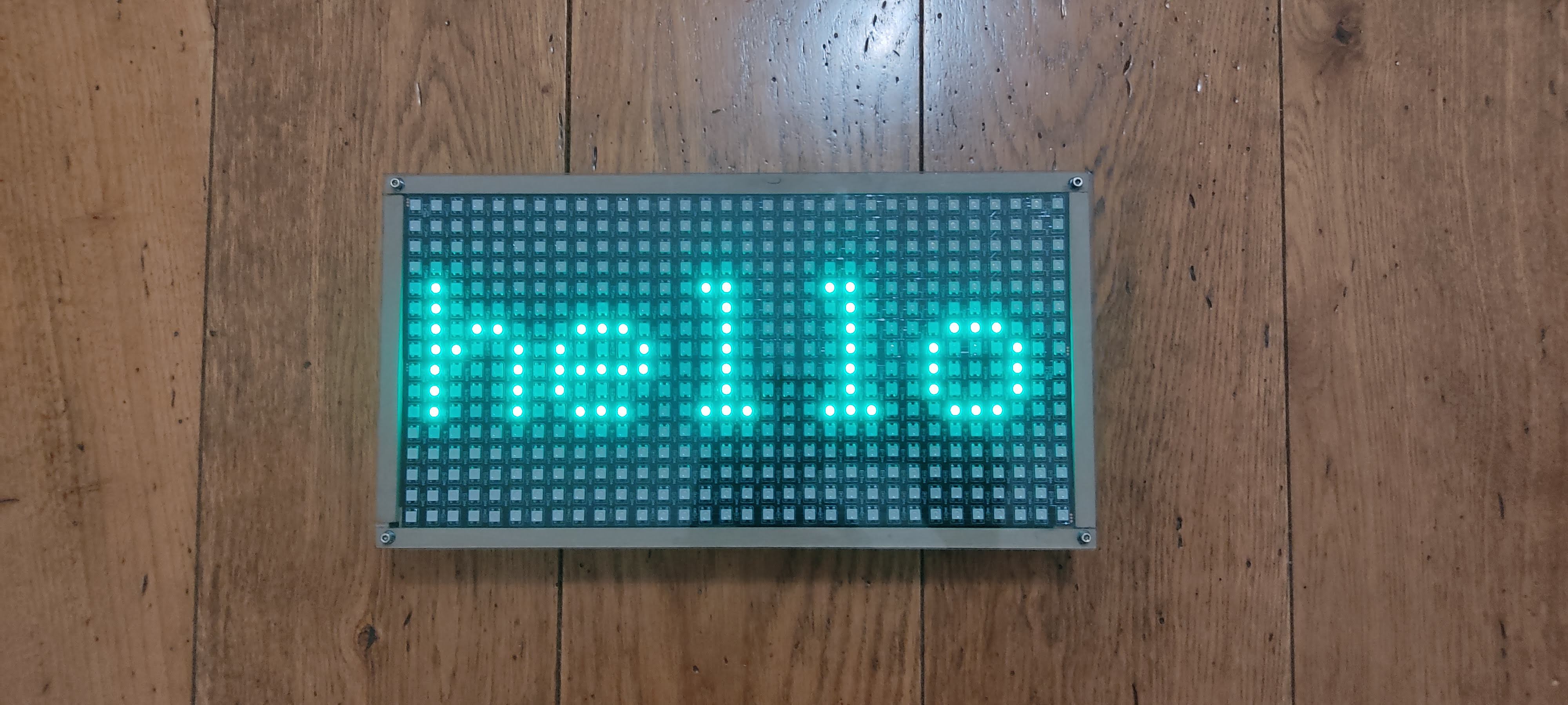
This is how the led box works:
Here are technical details.
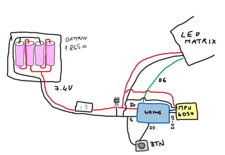
SCHEMA LED BOX PROJECT

There is a battery pack made with four 18650 batteries. I didn't have the charger circuit, so the whole box isn't directly rechargeable, but it should be in the future.
A switch turns the box on, then there is a 7805 IC to convert the voltage to 5V to power the led matrix the Wemos and the gyroscope (a better solution as a buck converter should be used to power the system and use all the pixels and wi-fi, but for now I've built it with things I have at home).
The board used is a Wemos d1 mini, which is based on ESP chipset.
The gyroscope/acceleremoter is the MPU-6050 which is connected to the Wemos with I2C communication through D1-D2 pins.
The led matrix is built with two 32x8 matrix panels and features 32x8x2 = 512 rgb leds powered by the batteries. The LEDs are organized as WS2812B strip and becomes a matrix with an Adafruit library that handles X,Y coordinates.
There is also a button that can be used to add features, for now it's used to turn on the Access Point to communicate to the led box with a smartphone. For this I've made a configuration panel that lets the user, for example, write some words on the display.
LED BOX MAIN SOFTWARE
To develop my projects, when they become more complex, I'm using the Platform.io framework on VScode. This allows me to use my everyday tools for developing as syntax references, code completion and code syntax colors.
The complete software is available on Github rep:
https://github.com/giuliopons/led-matrix-wemos/tree/main
It's actually in a "raw" state, it's not clean code. Maybe in future updates I will make it better.
It includes a captive portal that I've made and I use in my projects which has some HTML files that should be uploaded separately in the little FS of the Wemos.
Through the AP it's also possible to write letters in the matrix or activate an effect. The effect visible in the video is called "physical pixels'
The loop function performs just a continuous call to the "show" method, which change the frame of the animation based on the function chosen in the settings.
When the access point starts the same call to the "show" method is made by the captive portal code.
MOVING LEDS LIKE BALLS ON A PLANE
Key Features:
- Physical Simulation: Implements basic physics for particle movement, including acceleration, collisions, and boundary interactions.
- Real-Time Interaction: Reacts dynamically to device orientation using accelerometer data.
- Visual Representation: Displays the simulation on an LED matrix with color-coded particles.
All these features happen in the "liquidPixels " function.
This function simulates the movement of pixels in a LED matrix as if they were particles or balls interacting on a physical plane, influenced by the device's inclination (measured using an accelerometer). Below is a detailed breakdown of the function's operation:
- Reading Accelerometer Data:
- The function communicates with the MPU (accelerometer sensor) via the I2C interface to read acceleration values (
AcX,AcY,AcZ). - These raw acceleration values are extracted from specific registers of the MPU.
- The function communicates with the MPU (accelerometer sensor) via the I2C interface to read acceleration values (
- Angle Calculation (Roll and Pitch):
- The roll and pitch angles of the device are computed using trigonometric functions (via
FunctionsPitchRoll) applied to the accelerometer data. - These angles are adjusted with calibration offsets to account for sensor bias.
- The roll and pitch angles of the device are computed using trigonometric functions (via
- Calculating Movement Vectors:
- From the roll and pitch angles, movement vectors (
dx,dy) are derived to simulate the effect of gravity on the particles when the device is tilted.
- From the roll and pitch angles, movement vectors (
- Updating Pixel Positions:
- The LED matrix is cleared (
matrix.fillScreen(0)). - For each "particle" (
points[i]), the function calculates its new position based on its current velocity (vx,vy) and updates the position while considering:- Boundary Conditions: Particles bounce back if they hit the edges of the matrix, reversing their velocity components and applying a friction factor (
FRICTION). - Collision Detection: If a particle attempts to move to a position occupied by another particle:
- The relative velocity is calculated.
- Velocity adjustments simulate an elastic collision with some energy loss (due to
FRICTION).
- Boundary Conditions: Particles bounce back if they hit the edges of the matrix, reversing their velocity components and applying a friction factor (
- The LED matrix is cleared (
- Updating Velocity:
- The velocity of each particle is adjusted based on the tilt vectors (
dx,dy) to simulate the effect of gravity. - Friction is applied to slow down the particles gradually.
- The velocity of each particle is adjusted based on the tilt vectors (
- Rendering the Particles:
- Each particle's position is updated in the
occupancyarray, which tracks the grid occupancy of the matrix. - A color is calculated for each particle using the
calculateColorfunction, which likely maps velocity to color intensity or hue. - The particle is drawn at its new position using
matrix.drawPixel, and the updated matrix is displayed withmatrix.show().
- Each particle's position is updated in the
Other features:
- Write fixed strings and scrolling strings in any color

Next things to do:
- Rotate the box with words will rotate the words accordingly.
- A clock, why not?
- Flames effects
- Add a charging circuit
...more tbd...
 Giulio Pons