JP Gleyzes
Features
On an RC plane, propeller performance depends on pitch, diameter, profile, and material.
Testing your propellers will allow you to measure and improve their efficiency.
This motor + propeller test equipment will measure:
- Thrust
- RPM
- Current
- Voltage
- Electrical power
- Temperature
It can be controlled either manually via a servo tester or your radio transmitter/receiver or automatically via your Android phone.
And here is a video showing the system running
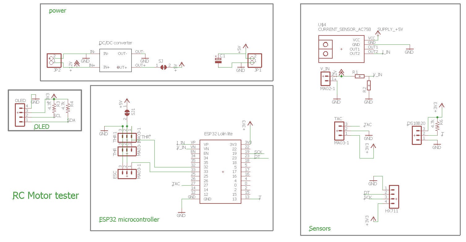
Schematics
- The heart of the system is based on a Lolin32 lite ESP32 microcontroler.
- Then a bunch of sensors are added to measure all the parameters.
- An Oled dispaly is (optionnaly) there to help debug or usage without smartphone
Bill of material can be found here : BoM
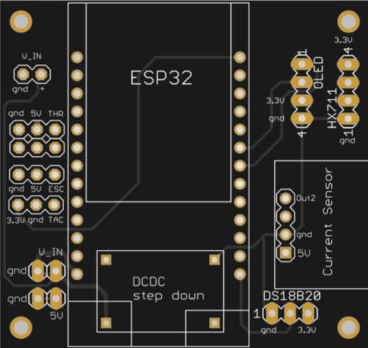
PCB
I have designed a nice and compact PCB allowing to fit the ESP32 and to connect all the sensors
The PCB was kindly sponsored by PCBWay and is as usual of excellent quality.

You can order it here: PCBWay shared project. It's cheap, delivered very fast and so professional looking!
And if you are new to PCBWay please use this affiliated link : https://pcbway.com/g/o35z4O
Power considerations
5V can be delivered either by the DC/DC converter (prefered solution) or directly by the ESC of your plane
power with DC/DC converter :
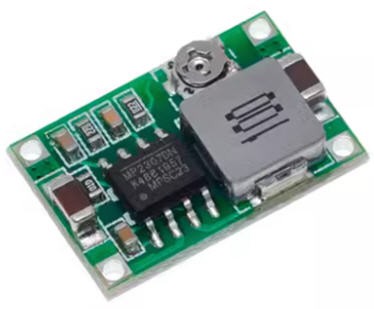
- first tune the trim pot value in order to get less than 5V (4.8V) output (do not power anything else before...)
- when this 5V is achieved, you can paint the trim pot with a drop of nail varnish to fix the potentiometer
- then (and only then) solder the SJ solder pad on the bottom side of the PCB. The 5V will now flow to the DFPlayer and the ESP32 (via the battery connector)
- Do not solder the SJ1 solder pad
using the DC/DC will insure a stable 5V supply which is used by the current sensor. Zero current is half the 5V supply. So this value ("5V") must be stable. If powered by the ESC, the "5V" could be as well 4.8V of 5.2V... this would induce a biais into the idle current measurement from ESC to ESC... So it's better to have a consistant "5V" which will allow to calibrate properly the current sensor.
Power with the ESC :
If your ESC is equiped with a strong enough BEC (1A for the ESP32) you can power the board and the ESP32 directly with the ESC connector :
- do not solder the SJ solder pad (nor the DCDC module if you want)
- solder the SJ1 solder pad
- connect the ESC servo pin header to the ESC connector on the board and power your ESC
I however do not recommand this second option (power with the ESC) as the 5V delivered by the ESC would change form ESC to ESC... see above...
Power with the USB plug :
It is safe but not reliable for exactly the same reason as above.
However you can power the device by the DC/DC converter (or the ESC) AND plug safely your USB to the PC for debugging purposes.
sensors
Five sensors are there to measure the parameters of your motor and propeller:
- ADC to measure battery voltage
- current sensor to measure current flowing into the motor
- IR sensor to measure rotation speed of the propeller
- temperature sensor to prevent over heating of the controller
- load cell sensor to measure the "weight" of the propeller (converted to thrust !)
Links for these sensors are provided into the bill of material
ADC
Voltage of the battery is directly measured by one of the ESP32 ADCs
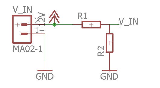
R1/R2 are a voltage divider needed to decrease the battery voltage to the ESP32 range (3V)
V_IN = R1 x Vbat / (R1 +R2)
So you have to be careful when selecting these resistors depending on the maximum voltage you plan to use for your battery.
Here are the values for a lipo 3s battery (my prefered setup!)
With R1 = 20k and R2 = 6.8k you will get max 3.3V with a fully charged lipo at 13V (3x 4.3V = 13V)
current sensor
To safely measure high current motors I have selected a powerful 100A current sensor : ACS758_100B
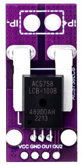
This sensor module is equiped with an operationnal amplifier on its OUT2 pin. So that you can input this pin safely on a micro controller ADC.
This sensor is "bidirectionnal" meaning that it can measure positive and negative currents. The zero value is at mid range of the ADC thus at 2.5V when the sensor is powered at 5V. This is totally withing the range of the ESP32 ADC specifications. (no need to change this OUT2 value if you measure values between 0 and 2.5V !)
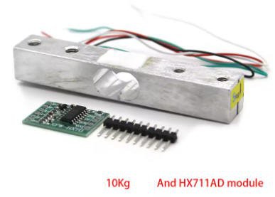
LoadCell
A loadcell will measure the thrust of the propeller.
I have choosen a 10kg loadcell. This device need an amplifier HX711 to adapt its value.
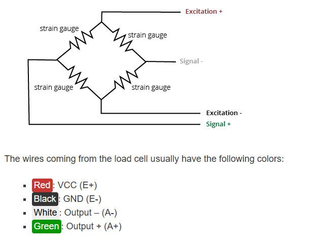
Connection between load cell and amplifier follows this schematics:
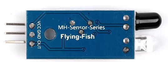
Propeller RPM
To measure the propeller speed we need to setup a tachometer. It will be made with an IR sensor. The reflection of the IR beam on the arms of the propeller will trigger interupts on the ESP32, and we will compute the rotation speed.
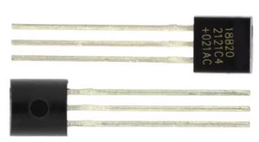
Temperature
A DS18B20 chip will take care of measuring the temperature of the ESC.
Basic wiring
Here is how the system should be connected to have a "basic" working condition:
- ESC is controlled by a servo tester
- current sensor is put in place between the ground and the negative side of the battery connector
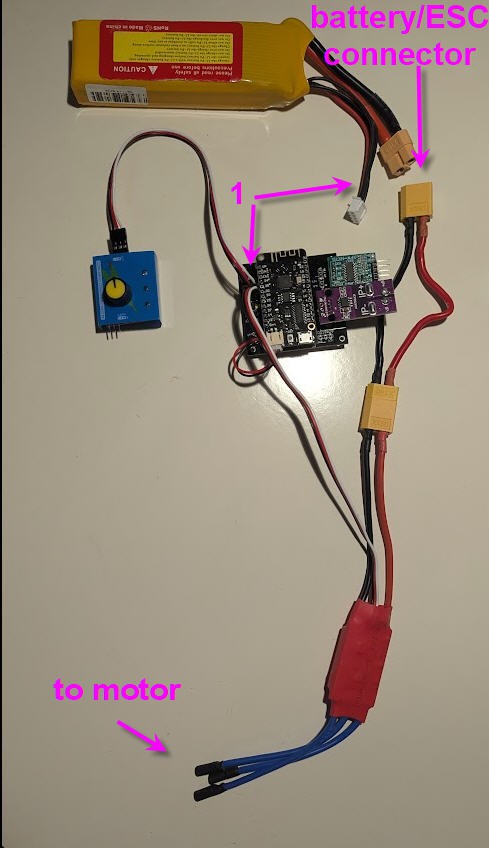
note that:
1) red wire of the balance plug of the battery should be connected to +V_in pin of the board
2) the load cell connector should be connected as well (not shown on the picture
3) the black wire from the ESC should go to IP- pin of the current sensor
4) IP+ pin of the current sensor shoud go to the negative wire of the battery pack
Software
ESP32 Firmware
Firmware is availble on my Github pages
This firmware needs to be as fast as possible for sensors acquisition. So all the sensors as acquired into the main loop and then sent to the Android application using UDP.
UDP is a "send and forget" protocol over IP. It is, by far, the fastest wireless protocol available to transfer data between computers.
So the firmware will take care of establishing the connection with the Android phone. This will be done automatically without having to enter any "manual handshake" by the user.
The only condition is that both the phone and the ESP32 are connected to your wifi router.
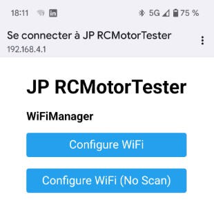
configuring the wifi
To configure the wifi simply follow this procedure:
I have used the ESP32 WifiManager library capabilities to enter wifi credentials on the ESP32 board.
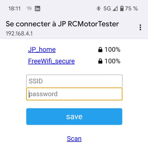
So if you boot the board (or reset it with the reset button) while touching the "GPIO15" touchpad on the lower right corner of the board, then the ESP32 exposes a Wifi hotspot (named "JP RCMotorTester" on which you can connect any smartphone (or PC)
Connecting to it will automatically open a configuration window
You then have to choose an exisitng wifi network for which you have the credentials, enter them into the form
Your ESP32 board is now configured to run with wifi and you would be able to monitor your motor with the android App
Reading the receiver channels
I found an excellent library to decode PWM Rx channels with embedded RMT hardware of the ESP32.
IMPORTANT : this library only works with version 1.0.6 of ESP32 Espressif board....
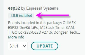
Using this library is fantastically simple (see the source code!)
I only use one channel which is either the servo tester or the throttle channel of your receiver.
//***************************
  //decoding the Radio receiver
  //***************************
  if (pwm_get_state_name(0) == "STABLE")  // if we receive "throttle" channel then switch to manual mode
  {
    // Reading the actual pulse width of Throttle channel
    throttle = constrain((pwm_get_rawPwm(0) - 1000), 0, 1000);  //clip throttle value between 0 and 1000

  }
Here the throttle channel. As you can see the output of the library is a standard pulse duration between 1ms to 2ms with a center position at 1.5ms
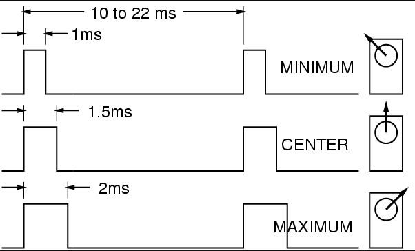
I remap this value between 0 and 1000 so that the throttle stick position has 1000 steps. Simple!
Then this value is processed to be sent to the ESC connector either directly or (auto modes) after being tuned.
Another library is used to generate the ESC servo signal :
// ESC output, PWM at 50Hz

#define ESC_PIN 33       // GPIO for ESC output
#include   //https://docs.arduino.cc/libraries/esp32servo/
Servo myESC;             // create servo object to control an ESC
and the pulse is computed and output on the ESC_PIN
// Do something with the pulse width... throttle
  // ESC PWM
  switch (opMode) {
    case 0:                                      //manual
      myESC.writeMicroseconds(throttle + 1000);  //replicate the throttle value
      break;
    case 1:  //step
      if ((millis() - refreshTimeOut) > refreshDelay) {
        refreshTimeOut = millis();
        currentThrottle += refreshStep;
        refreshStep = -refreshStep;
      }
      throttle = currentThrottle;
      myESC.writeMicroseconds(throttle + 1000);  //generate the step
      break;
    case 2:  //sweep
      if ((millis() - refreshTimeOut) > refreshDelay) {
        refreshTimeOut = millis();
        currentThrottle += refreshStep;
        if (currentThrottle >= maxThrottle) refreshStep = -refreshStep;
        if (currentThrottle <= minThrottle) refreshStep = -refreshStep;
      }
      throttle = currentThrottle;
      myESC.writeMicroseconds(throttle + 1000);  //generate the step
      break;
    case 3:                               //stop
      myESC.writeMicroseconds(0 + 1000);  //clear the throttle value
      break;
    default:
      // statements
      break;
  }
values to tune the operationnal mode are set into the Android application
Android Application
Android App is available on my Github pages
You can compile the source code using B4X freeware compiler or use directly the .apk file available into the github project.
When installing the App you will get warnings saying that this App is "old", go on installing it it is safe!
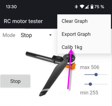
Using the App is very very simple:
- launch it
- look at the points arriving into the screen !
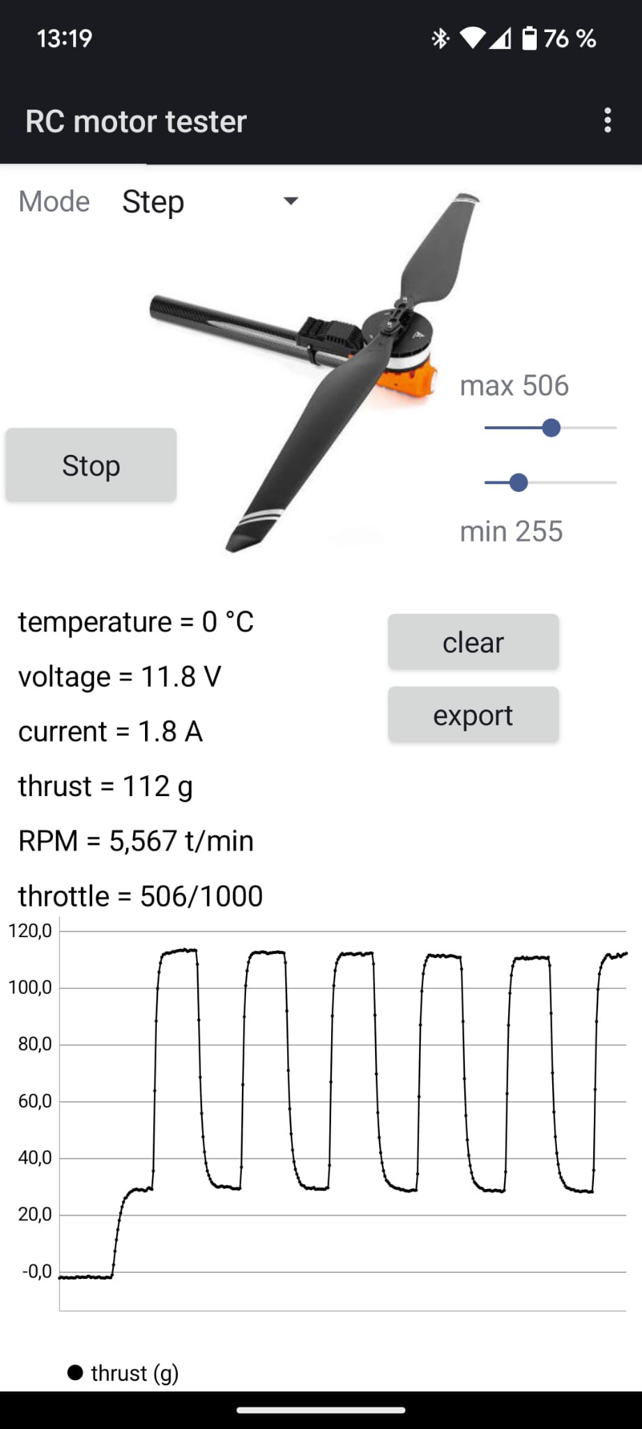
- click on the labels : temperature, voltage, ..., throttle to change the display
- click and zoom on the curve to analyse it
- click on the "clear button" to ... clear the curve
- click on the "export" button to export all the acquisition (even the oldest hidden part of the curves). The file will be saved into the "download" folder of your phone. It is a text file that you can import into excel.
- change the mode of operation between:
- manual : throttle control is done either by your RC receiver or servo tester
- step : will perform steps between min and max throttle values
- sweep : will perform a saw teeth pattern between min and max
- stop : stops the motor
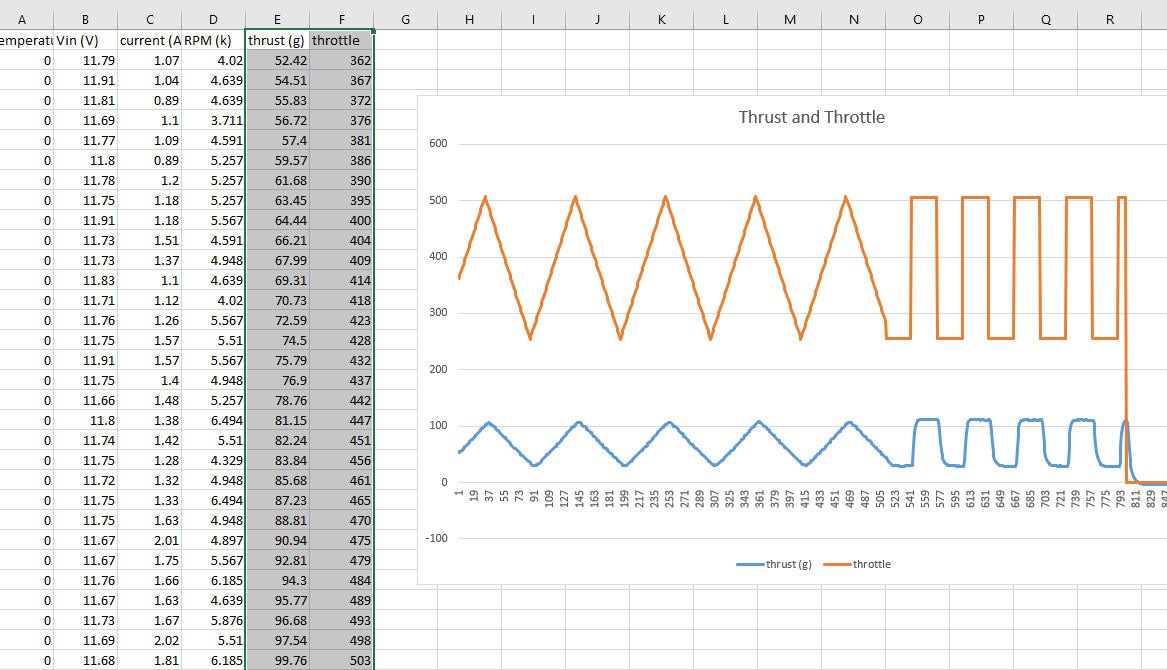
Here is another screenshot showing two successive acquisitions "sweep" followed by "step"

Finally, into the top right 3 dots menu you can access to the calibration of the load cell.
What you will have to do is to start the system (motor off) and the arm horizontal. Then (when some points arrive) attach a 1kg load to the spinner and launch the calibration (not the motor !)... That's it your load cell is calibrated and will keep this value.
During start up two other calibrations are performed :
- "tare" of the loadcell. This will "erase" the weights of the propeller and of the motor
- calibration of the zero current of the hall sensor
Due to these calibrations, which can last around 10s, do not start your motor before you see new points coming into the curves...
Excel export
Here is an example file when using the "export" button.
You can open this file into a spreadsheet and do what you want with the data !
comparison with on line calculators
I did try this excellent online motor calc
Just enter the parameters into the boxes and you will get a pretty good estimation of your drive system
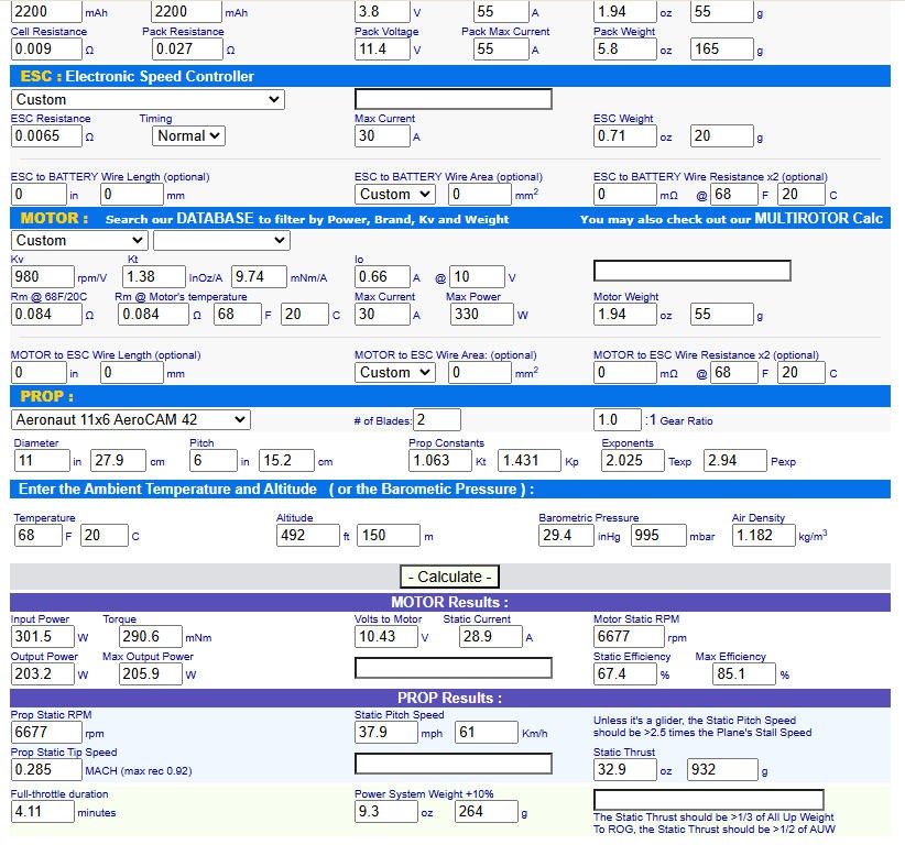
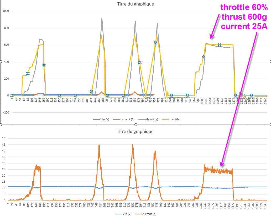
932g of static thrust at 28.9A static current
Look at the "saw teeth" in the middle of the next graphic : 900g of thrust at 35/40A (too much for my motor that's why I did limit the throttle at 60% full)
troubleshooting :
If the acquisition of new oints do not start, it likely to be a problem into the communication protocol. Try these tricks:
- close the App (do not kill it) use right button or right to left swipe
- if it still do not work try to reboot your wifi router (I had to do it with my freebox...)
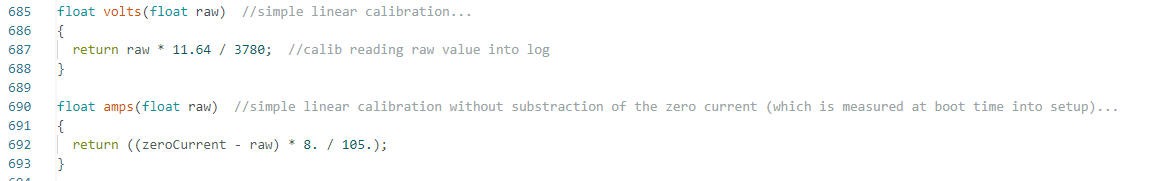
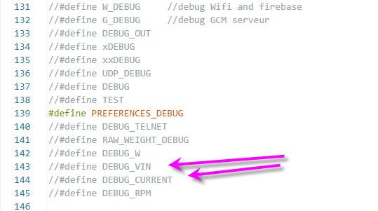
If the calibrations of current and voltage are not precise enough... plug an ampere meter and a volt meter into the battery, un comment the DEBUG_VIN and DEBUG_CURRENT lines and read the log file into t your Arduino IDE...
Then change the calibration values accordingly into the volts() and amps() functions, and recompile the ES32 firmware