 Jeremy
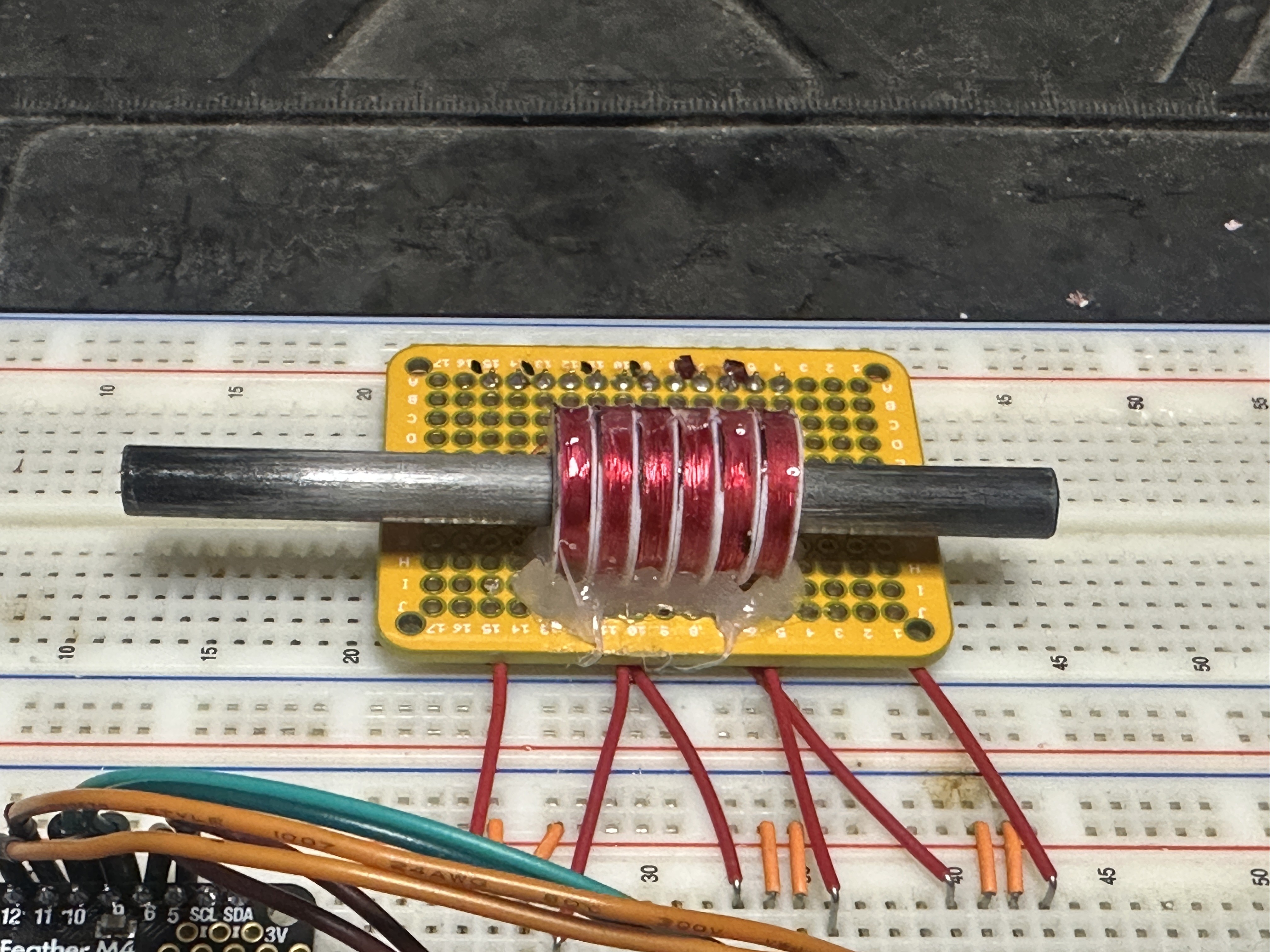
I learned from a bunch of mistakes on my first version, and it moves so much better! I'll explain all the changes, but first, take a look!
Coil width
Only after painstakingly winding the coils on my first version I realized I had made some miscalculations, and each coil was 1mm too wide. The six coils are arranged into two groups of A, B, and C. The width of the coils needs to line up with the arrangement of the magnets so that there is the same magnet alignment in the first group of coils and the second. If this is wrong, the magnets will only line up with one group at a time, and the movement will be jumpy.
In this version, the coils are 2.6mm wide, with 0.8mm separators between them. This lines up with each magnet pair being 6.35mm wide, separated by 4mm spacers.
MAGNET PAIR + SPACER = (COIL + COIL SEPARATOR) * 3
The width of one magnet pair and a magnet spacer should equal the width of three coils and coil separators.
Coil Fabrication
The other problem with the first version was I had 3D printed a single coil spool bobbin with separators for all six coils.
On paper, this seems like a great idea. You can precisely control the width of all the coils, and they'll be perfectly aligned. The problem comes when you've wound all six coils, and a wire on one of the coils breaks. Now, you have to start over fresh.
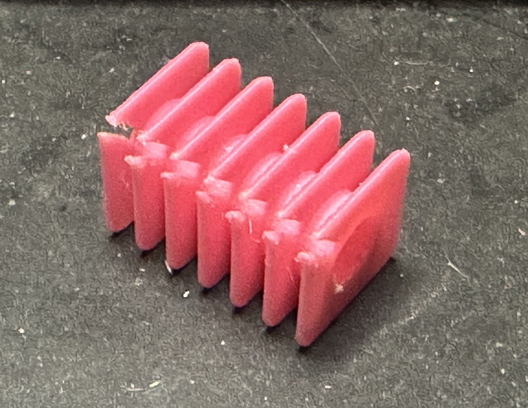
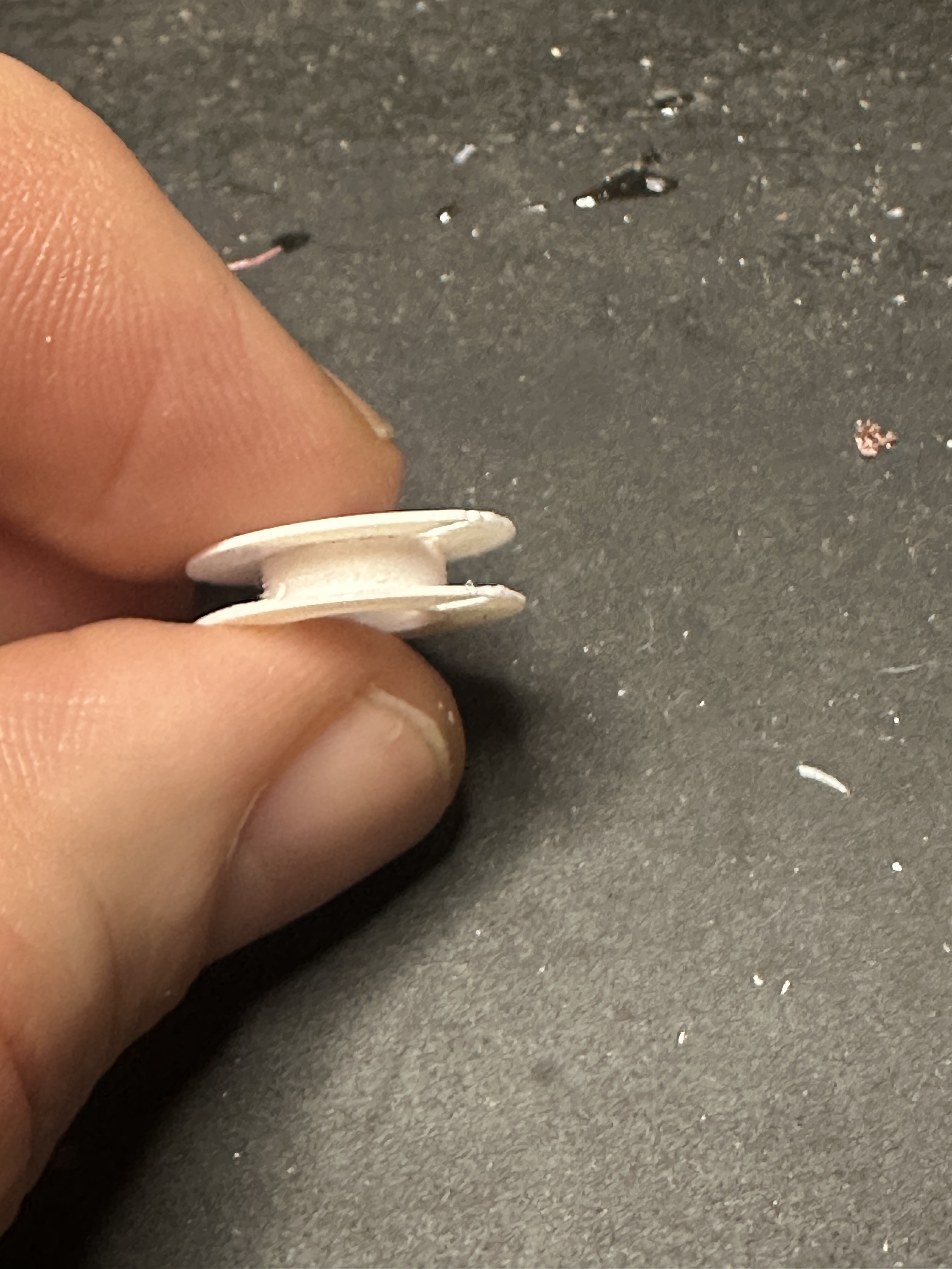
For this version, I decided to wind each coil independently. To easily print without worrying about overhangs or support, I designed each bobbin to be printed as two pieces whose tubes would nestle together into a single bobbin. You can find the 3D printable files in the github repo.
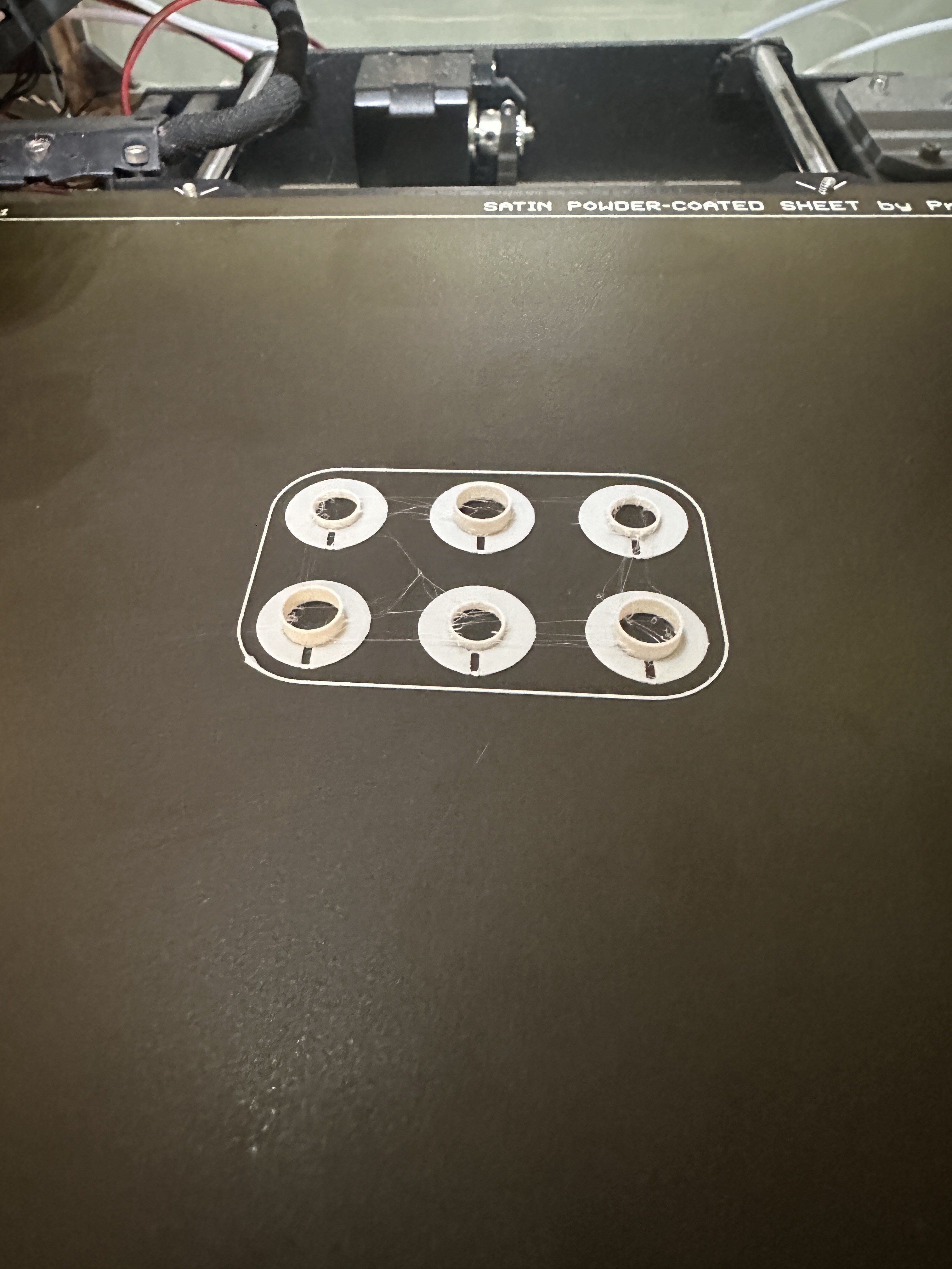
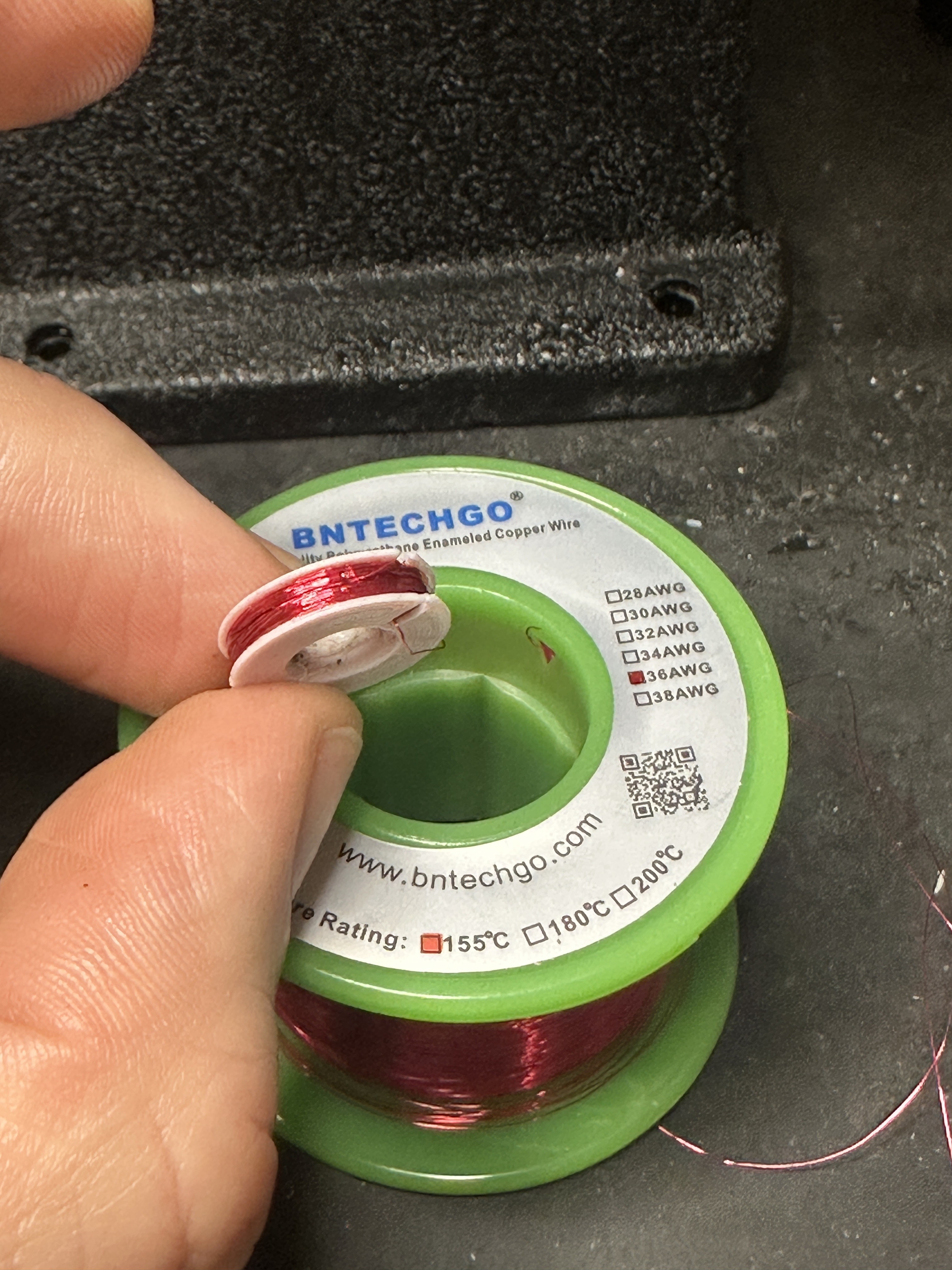
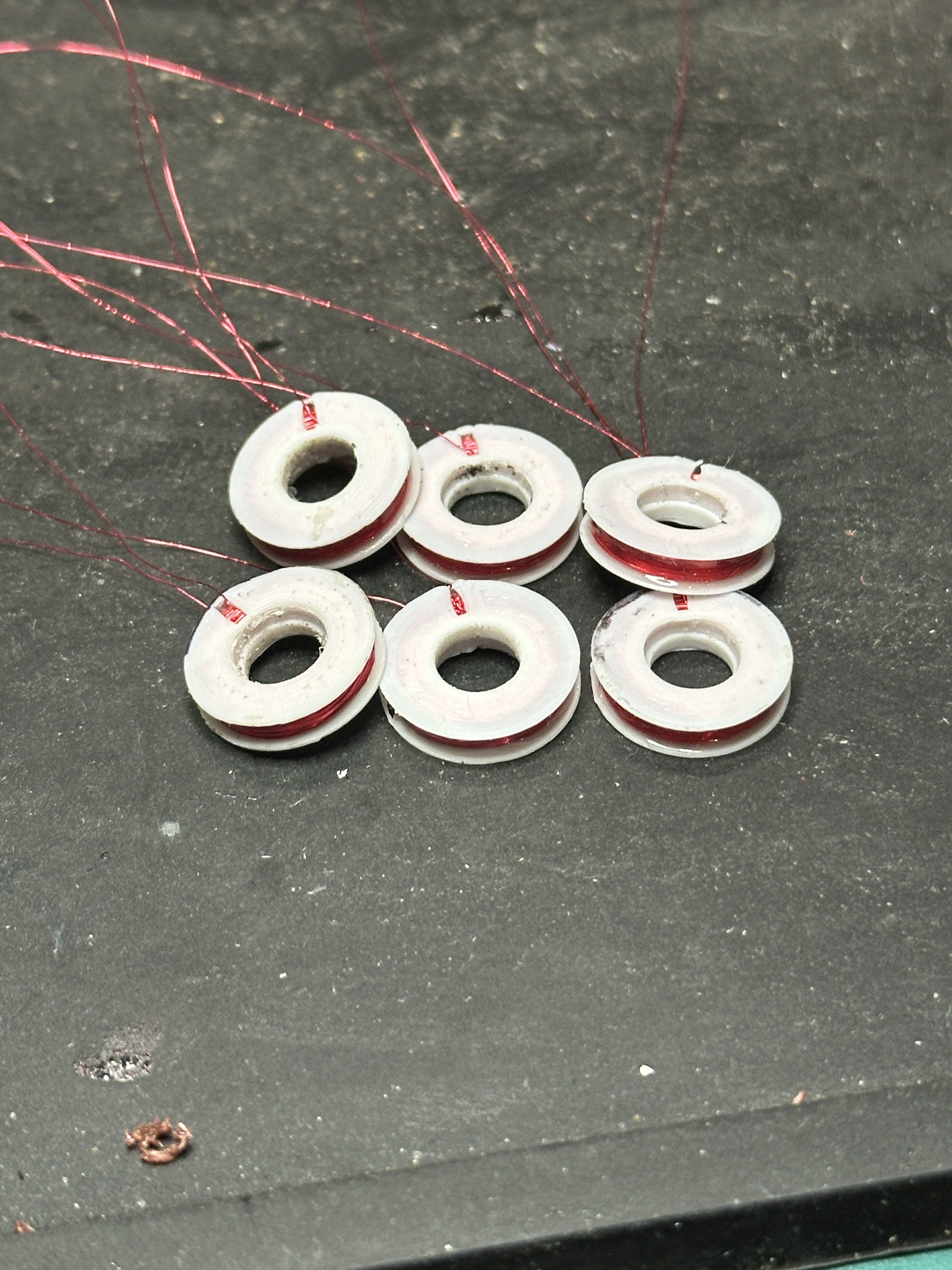
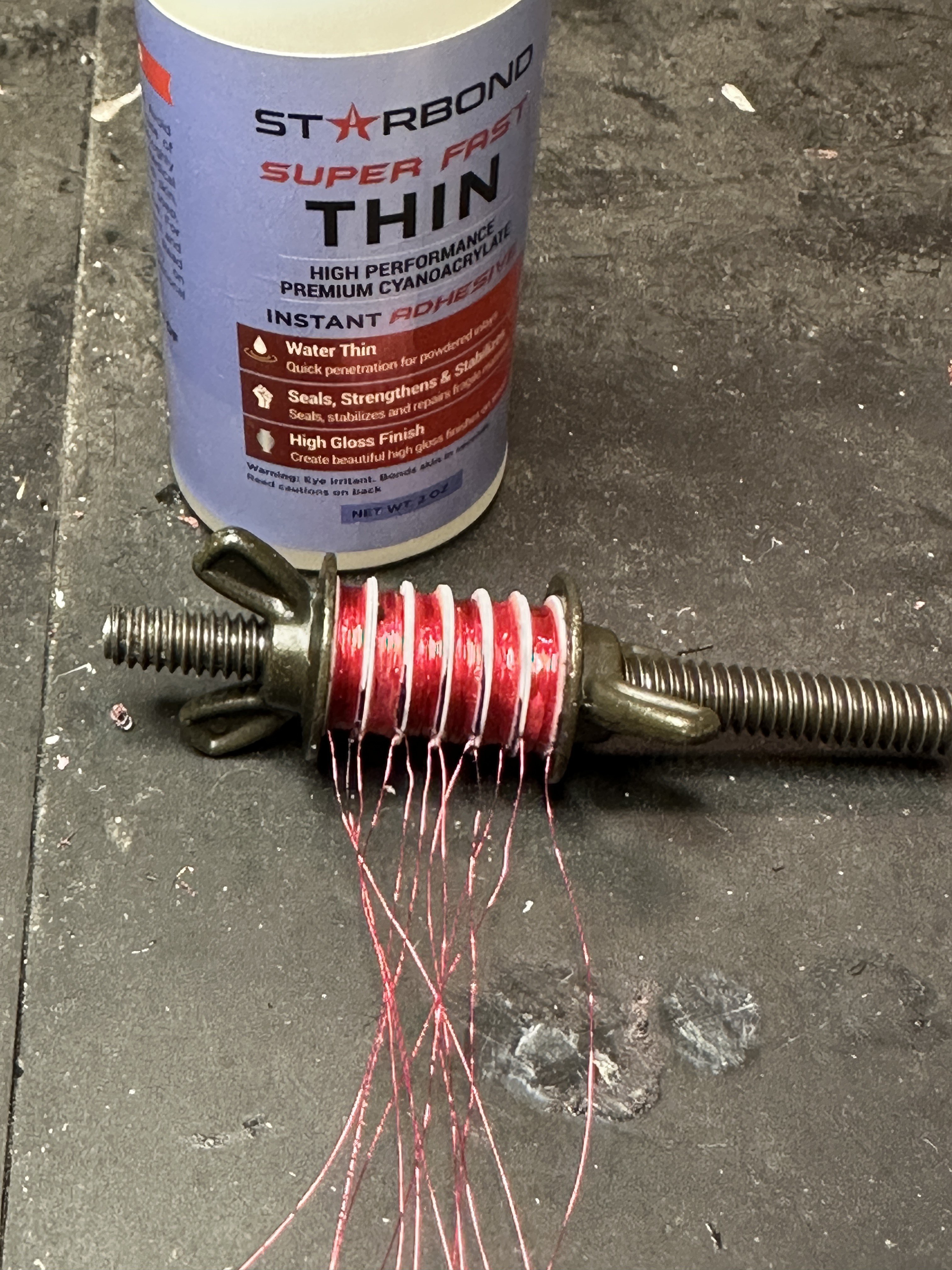
I gave each coil 300 turns of AWG 36 magnet wire, and then I added a layer of epoxy around the coils to secure the wires. To combine them into a single unit, I hit them with superglue and clamped the whole thing on a threaded rod with wingnuts and washers.
Lastly, I hot glued the assembly onto a perf board and soldered the wires into place.
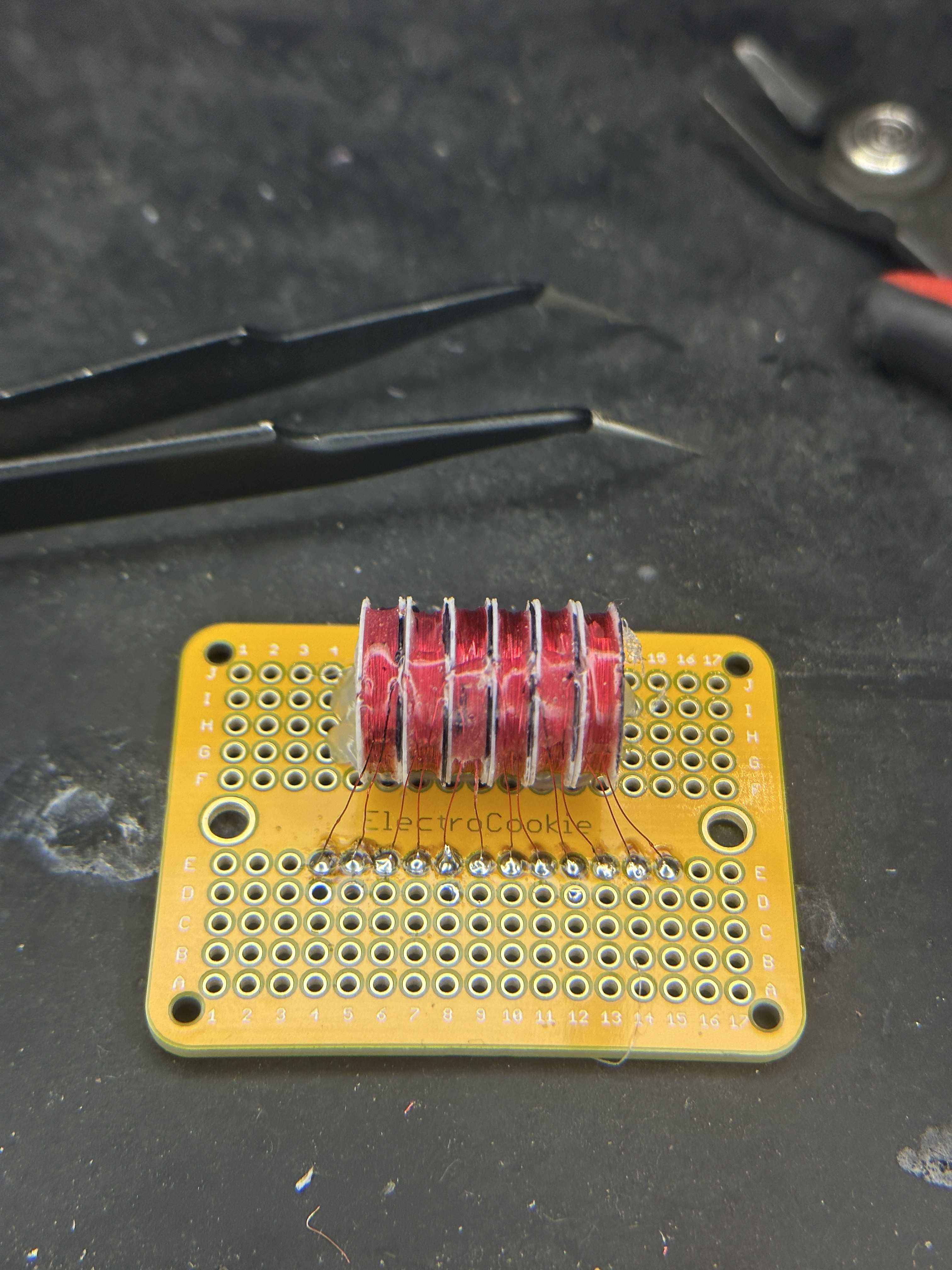
Each coil is about 16Ω, and I wanted the flexibility of powering the coils up to 6v, so I connected each pair of coils together. A/A', B/B', and C/C'. It's important that the second coils (denoted with the apostrophe) need to be in reverse polarity with the first coils. To achieve this, I connected the second coils in reverse of the first ones. For example, when looking at each coil, their wires are labeled from left to right as 1 and 2:
- Coi A, wire 1 -> Motor driver output OA
- Coil A, wire 2 -> Coil A', wire 2
- Coil A', wire 1 - Motor driver output OA
This wiring arrangement should swap the magnetic polarity of the second coil.
Code
Original sine wave program
After all this, the movement still wasn't great. It was jumpy and sometimes moved backward for a step before jumping forward. The original program used three sine waves, each offset by 120 degrees from the other, to determine the current for each phase at each step (see my explanation in my last post),
But here's the problem: look at phases C and A' in these two steps:
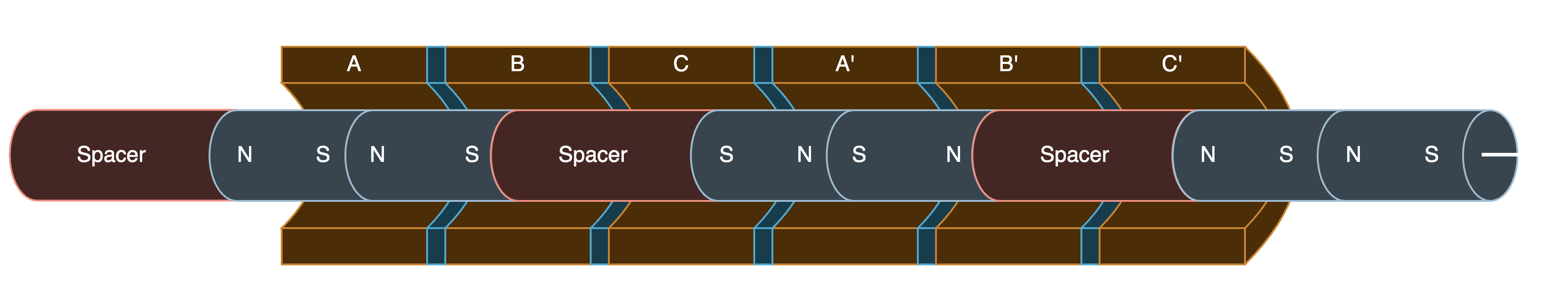
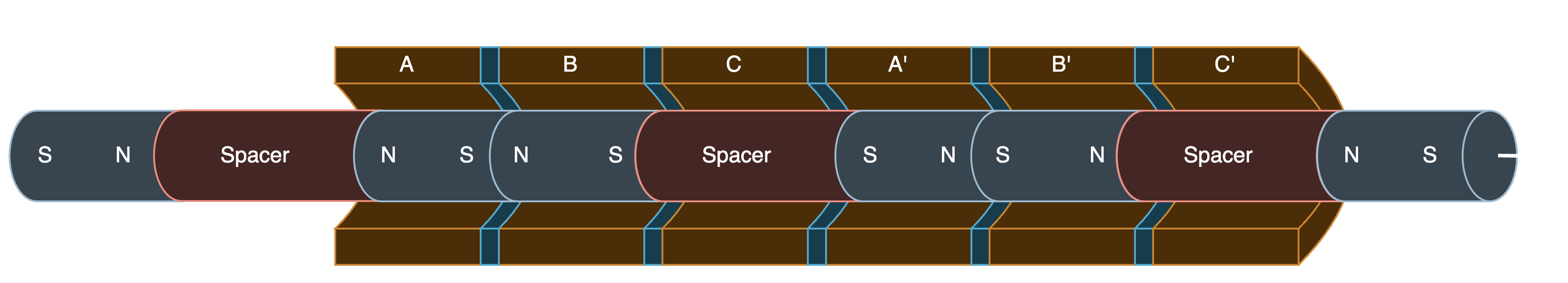
In the second step, the pusher is supposed to move toward the right and align the magnets under A/B and A'/B'. But, phase C' is at -100%, which likely pulls the pusher back to the left. In the step after this, B' becomes -100%, and C' is reduced to -50%. This then jumps the pusher back towards the right.
I spent a lot of time researching how to recalculate the curves to avoid this. I could never figure it out, so please let me know if anyone else has the answer.
In the end, I went with a different approach...
PWM lookup table
In this program, I created a lookup table of the current output for each phase, for each step, from -100% to +100% in 25% increments for a complete cycle. The program then interpolates phases between each step to smooth the motion. For the video at the top, the program makes 10 steps for each step in the lookup table.
STEPS = [
  [25, 0, -75 ],
  [50, 0, -50 ],
  [75, 0, -25 ],
  [100, 0, 0 ],
  [75, 25, 0 ],
  [50, 50, 0 ],
  [25, 75, 0 ],
  [0, 100, 0 ],
  [0,  75, 25 ],
  [0, 50, 50 ],
  [0,  25, 75 ],
  [0,  0, 100 ],
  [-25,  0, 75 ],
  [-50, 0, 50 ],
  [-75, 0, 25 ],
  [-100, 0, 0 ],
  [-75, -25, 0 ],
  [-50, -50, 0 ],
  [-25,  -75, 0 ],
  [0, -100, 0 ],
  [0, -75, -25, ],
  [0, -50, -50 ],
  [0, -25, -75 ],
  [0, 0, -100 ],
]
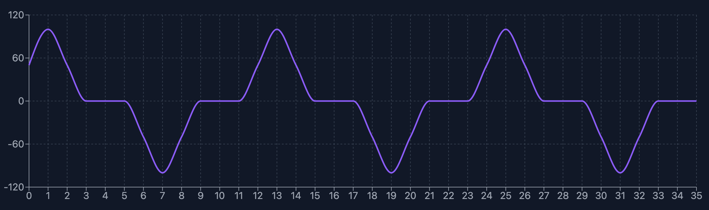
As you can see, each coil is completely off for 20% of its cycle. Graphed, the curve roughly looks like this for each coil.
Force output
The force output of the actuator is still quite small. I haven't measured it, but it's easy to stop the pusher with my finger with almost no force at all.
Discussions
Become a Hackaday.io Member
Create an account to leave a comment. Already have an account? Log In.