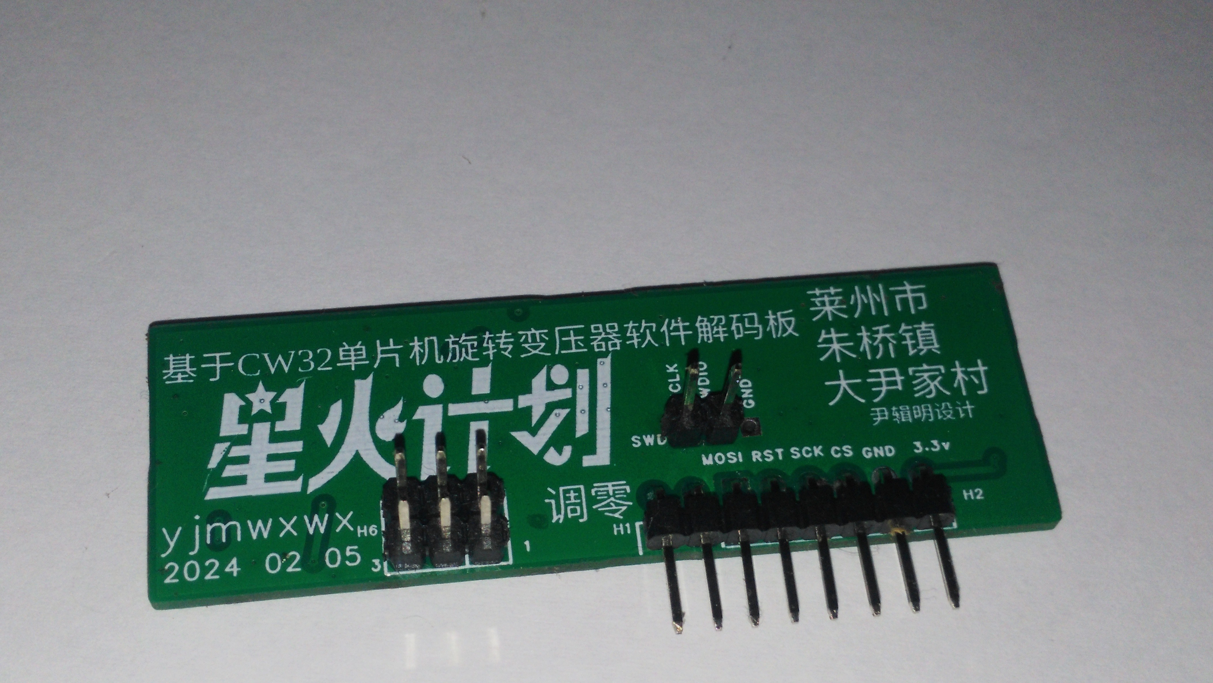
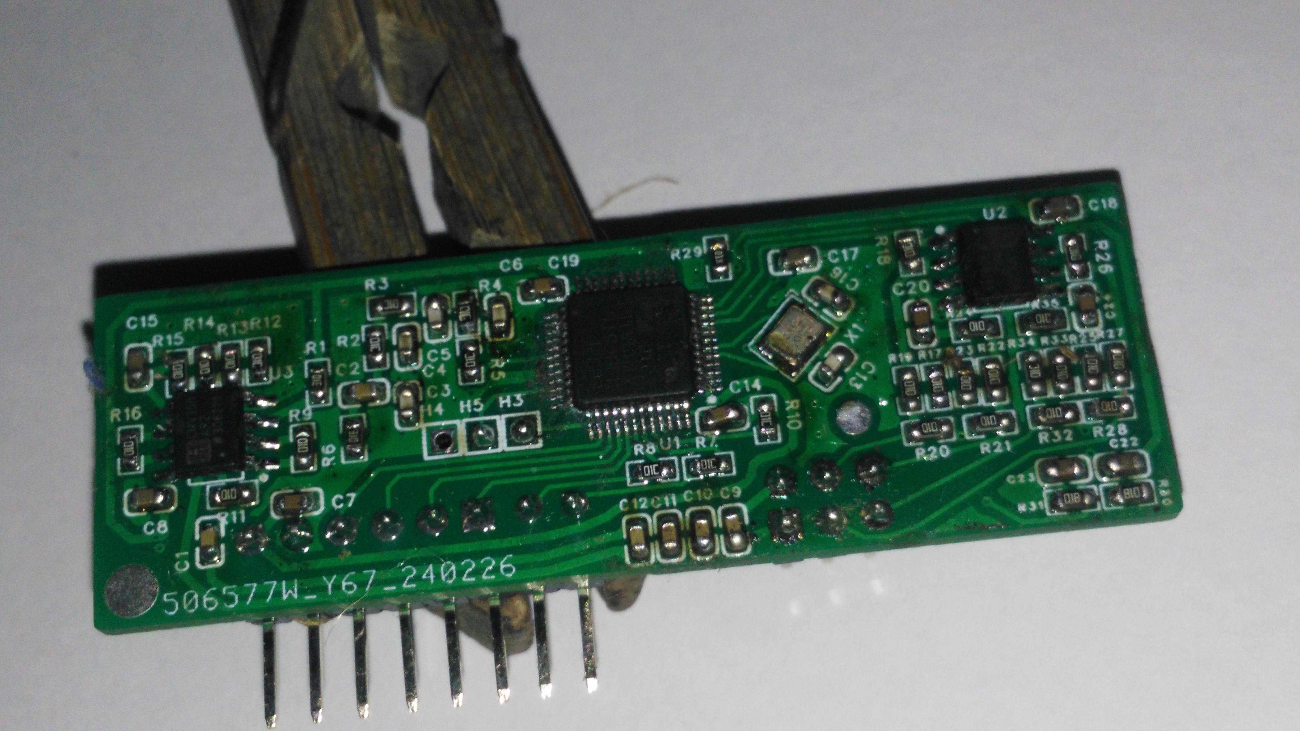
Recently studied motor control, bought a sedan power steering motor, position feedback is used in the resolver, this sensor is also often used in new energy electric vehicle motors, dedicated chip I heard is more expensive, so I used the microcontroller to make their own decoder board.
Supply voltage +3.3V suitable for battery power supply, data update rate of 10,000 times per second, data resolution (0-36000 last jump counted as 12-bit), bandwidth 1591 Hz (I do not understand what the bandwidth means), the theoretical tracking speed of up to 95,500 revolutions per minute (untested)
spi host single transmitter mode, format 16-bit, MSB in the front, serial clock phase configuration leading edge sampling / trailing edge shifting, serial clock polarity configuration standby low, receive slave machine needs to be powered up first.
I have not messed with microcontrollers communicating with each other before, so I made it a single transmit mode, and after sending 1 a data CS pulls high.
Rotary change any angle automatic zero correction method:
CW32 43 feet pull down and then pull up into the angle of the automatic zero program, the new burned microcontroller must perform this operation, automatically adjust the zero deviation should be repeated after zero adjustment!
Matching different rotary need to change the capacitance of the excitation coil in parallel, that is, the four 103 capacitors, you need to use the LCR meter to measure the rotary excitation coil reactance, for example, I'm +200 ohms or so, I'll be connected to the four 103 capacitors.
Hardware part:
The use of microcontroller output a 20KHZ PWM, amplified by the LMV to drive the rotary excitation coil, another op-amp inverted, connected to another excitation line, COS and SIN into the differential amplification into the microcontroller two ADC port.
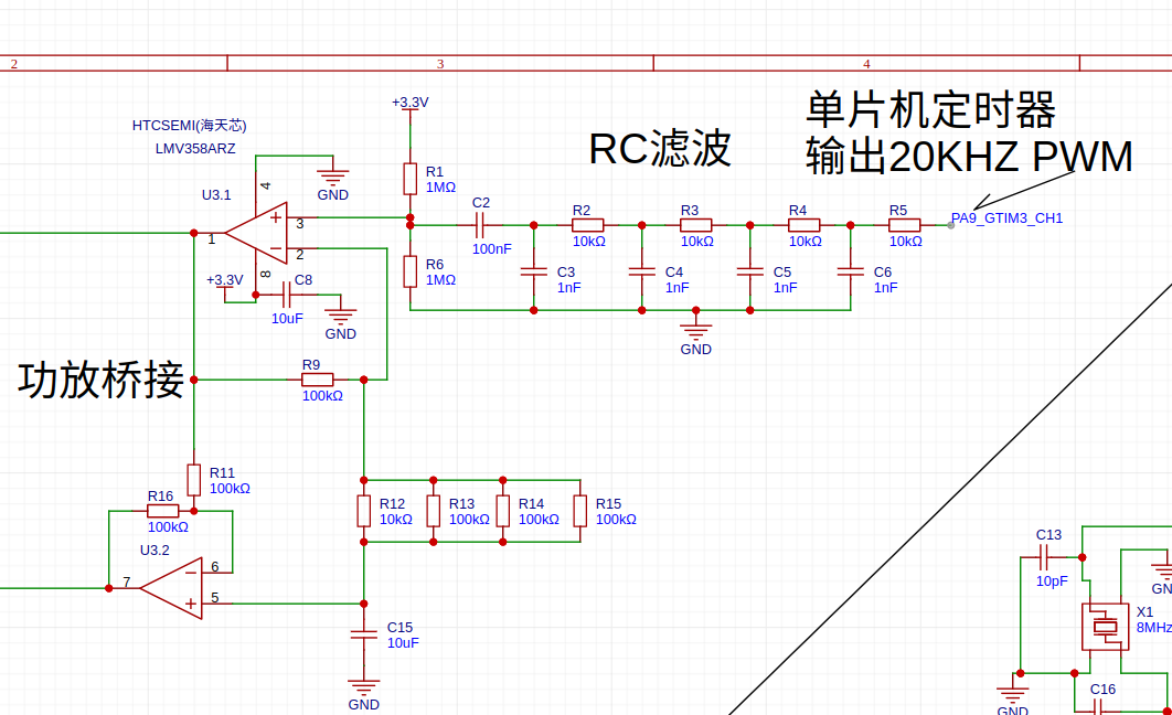
Microcontroller output all the way 20KHZ PWM, after RC filtered into a sine wave, and then into the op-amp amplification, another op-amp inverted, the two op-amps a drive resolver.
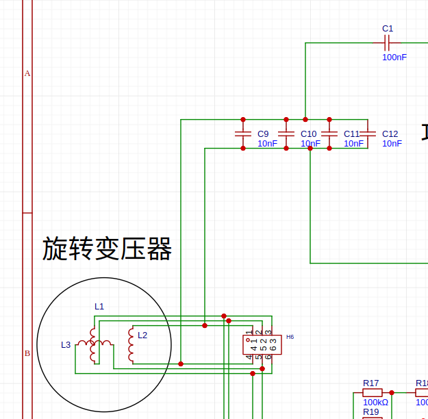
Measure the rotary transformer inductance with an LCR meter and then connect capacitors in parallel to make the resonance frequency the same as the drive frequency, C1 to increase stability.
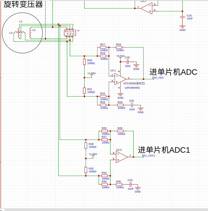
The resolver COS and SIN go to the two differential amplifiers and then to the two ADC ports of the microcontroller respectively
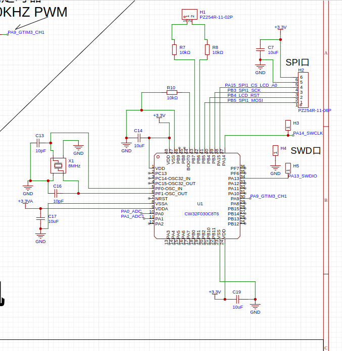
CW32 Microcontroller Circuit
Software part:
Microcontroller each port corresponds to the sampling rate is 1MHZ, collect 100 points after the interrupt, using the DFT to calculate the collected COS and SIN sequence of real and imaginary parts, rotate the phase to 0 degrees, with the real part of the ATAN2 into the calculation of the angle, the current angle is saved to the register, such as measuring the next angle after the phase subtraction calculation of the difference in the angle, and then calculate the angle difference between the COS and the SIN, feedback back to the ATAN2 before the rotation into the ATAN2 angle to realize the phase lock, so that the angle obtained does not matter with the speed, offsetting the system delay.
phase shift calculation
zhuansu = 95500
shijian = 100
xiangyi =90-atan2(159155 / (zhuansu / 60), shijian)*180/3.1415927
1.s is the source code, 1.bin is the firmware, respectively, there are two programs, one is directly using COS12864 to show the angle, two outside one through the SPI port output, get the data to be processed immediately, otherwise the motor speed is high when there will be a large phase shift.
 yjmwxwx