Introduction
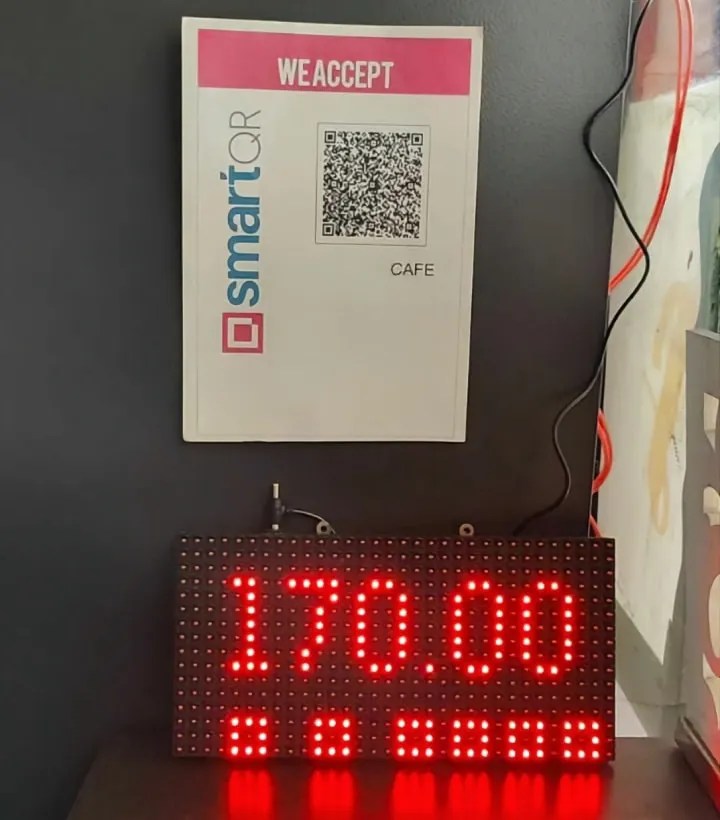
The Smart Payment Display is an innovative system designed to automate and simplify payment status notifications for businesses. It uses an ESP12F microcontroller, a P10 LED matrix display, and a server-based system to display real-time updates about payment transactions. This project provides an efficient way for businesses, such as retail stores, parking lots, or service counters, to confirm payments visually, ensuring quick and transparent communication with customers.
FOR FULL PROJECT:
https://electronicsworkshops.com/2024/10/26/smart-payment-display-using-p10-led-matrix-and-esp12f/

Key Components
ESP12F Microcontroller:
A low-power Wi-Fi-enabled microcontroller that serves as the brain of the project, managing network communication and controlling the display.
P10 LED Matrix Display:
A 32×16 LED panel used to visually display messages such as payment status and amount. Its bright output makes it suitable for both indoor and outdoor environments.
Server:
A backend system (cloud-based or local) that processes and stores payment transaction details. It provides an API endpoint for the ESP12F to fetch payment statuses.
Power Supply:
A stable power source to drive the ESP12F and the LED matrix display.
Wi-Fi Network:
Provides internet connectivity for the ESP12F to communicate with the server.
Working Principle

System Initialization:
- When the system is powered on, the ESP12F connects to the Wi-Fi network using pre-configured credentials.
- Once connected, the microcontroller is ready to interact with the server.
Payment Monitoring:
- A server handles payment information. This could be from an online payment gateway or a Point of Sale (POS) system integrated with the backend.
- When a customer makes a payment, the server updates the transaction status.
Data Retrieval:
- The ESP12F sends periodic requests to the server via a RESTful API to fetch the latest payment status. The request might include specific identifiers like transaction IDs to retrieve relevant data.
- The server responds with payment details, including the status (e.g., “Paid” or “Pending”) and the transaction amount.
Data Processing:
- The ESP12F processes the server response. If the payment status is marked as “Paid,” the amount is extracted. If no payment is detected, the system displays a default message such as “Awaiting Payment.”
Display Update:
- The ESP12F sends the processed data to the P10 LED matrix for display.
- For example, if the payment is successful, the display shows:
“Payment Received: Rs. 500”
If the payment is pending, it displays:
“Awaiting Payment…”
Real-Time Feedback:
- The system continuously polls the server at regular intervals (e.g., every 10 seconds) to ensure the display reflects real-time updates.
Error Handling:
- If the server is unreachable or the response is invalid, the display shows an error message like “Connection Error” to inform users of a potential issue.
Applications
- Automation: Removes the need for manual confirmation of payments, reducing errors and improving efficiency.
- Real-Time Updates: Reflects the latest payment status almost instantly.
- User-Friendly Interface: Provides a clear and visible display for customers and staff.
- Scalability: Can be easily integrated with various payment systems and expanded for multiple counters.
- Low Cost: Utilizes affordable hardware components and a simple software architecture.
PCB Files

3D files

Real Image

Manufacturing Files
Gerber
Order Directly from PCB WAY
I have already uploaded all these required manufacturing files in PCBWAY website. You can easily go to the below link and place you order, and get your Own Home Automation PCB manufactured from one of the best pcb manufacturer PCBWAY
Conclusion
This project demonstrates how smart IoT systems can transform payment processing into a transparent and efficient experience.
FOR FULL PROJECT:
https://electronicsworkshops.com/2024/10/26/smart-payment-display-using-p10-led-matrix-and-esp12f/
 electronicsworkshops