 Hans Jørgen Grimstad
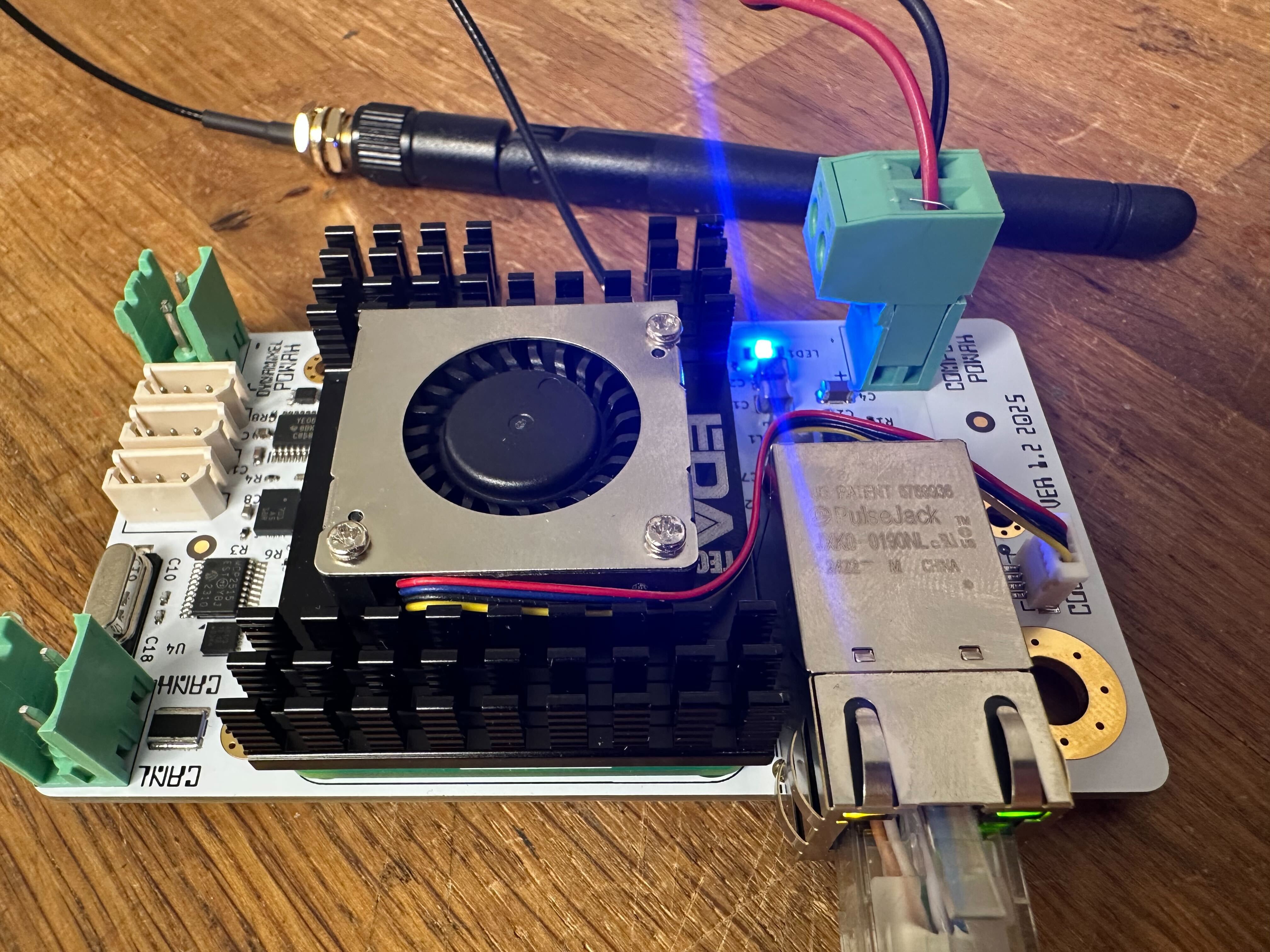
A couple of facpalms later and I have a glorious new revision of the board!
Fixes in revision 1.2:
- Correct wiring of the MCP2515 CAN Controller interrupt pin.
- Correct wiring of the DXL_DIR signal that goes to the the NC7WZ241K8X buffer via a TXB level shifter (3.3V logic levels on the board and the Dynamixel servos require 5V logic for the half duplex data line).
- Remapped I2C so it is using GPIO3 for SCL and GPIO2 for SDA.
New features in revision 1.2:
- Wired ethernet (makes life a bit easier for ad hoc connections / testing). This was also a nice excuse for me to familiarize myself with differential pair routing in KiCAD :)
- Active PWM cooler (Added a JST BM04B-SRSS-TB 4 pin connector for 5V, GND, PWM and TACHO)
- Mounting option for SMA connector / Antenna
Initial testing is promising. Current status is as follows:
- Both network interfaces are ok.
- I2C is ok. IMU is detected.
- SPI is ok.
- CAN is ok.
- Fan PWM control is ok.
Next up is to verify that the Dynamixel side of the board is ok. It is basically the same circuit that I have used on several other boards, so I don't expect any surprises (famous last words... :))
At some point I guess I'll have no choice, but to build a couple of demonstrator robots for the board (and maybe look into a realtime kernel if I run into strict timing requirements somewhere). My AX-12A based hexapod is an obvious choice for testing the board with Dynamixel servos. I havent decided on a CyberGear project yet. I biped would be fun, but that would get expensive real fast, so maybe I'll settle for a simple robot arm project (Maybe CyberGear joints + Dynamixel grippers ?) .
Discussions
Become a Hackaday.io Member
Create an account to leave a comment. Already have an account? Log In.