 Florian B.
Time measurement with CPLD
My initial approach for time measurement was to utilize the Input capture feature of the Arduino UNO's timer1.
Another option to measure the time is by utilizing a CPLD. With this I can measure up to signals of up to 4 signals. We can apply digital delays and signal debouncing. I am using an older but hobbyist friendly 5V tolerant and thus "Arduino compatible" EPM7128SLC84-15 for this. This device limits the acquisition to 4 Pulses with a maximum time count of 13 bits. With a more powerful device more bits and more signals can be measured but for my experiments this is just enough.
The following VHDL code implements such a time measurement counter.
A measurement is initiated with a High-Low-Transition of the TRIG Signal. This event will start a Time Counter. that is clocked with externally provided 16MHz clock pulses at COUNT_CLK. After a time delay it accepts Low signals at input SIG and records the time. Up to 4 signals can be measured with a resolution of 13 bits.
The Arduino reads the counter value in chunks of 4 bit nibbles adressed by A0 and A1. The data is available at the Data port D0..D3. Before the first read out READ_RES is set to Low and a negative Clock pulse is applied at READ_CLK. After all nibbles are read the read counter can be advanced by setting READ_INC to High and applying another READ_CLK pulse. Values are combined in the Arduino sketch.
Signals are:
- COUNT_CLK - Input for external clock Into CPLD
- TRIG - Input for Trigger pulse
- SIG - Input for digitized Signal pulse
- READ_CLK - Clock Input for read interface
- READ_RES - Reset Input for read interface (to reset to first measured signal)
- READ_INC - Increment Input for read interface (to advance to next measured signal)
- A0, A1 - Nibble select input to select the counter nibbles
- D0,D1,D2,D3 - Data output port to transmit data to the Arduino
    library IEEE;
    use IEEE.STD_LOGIC_1164.ALL;
    use IEEE.NUMERIC_STD.ALL;

    library IEEE;
    use IEEE.STD_LOGIC_1164.ALL;
    use IEEE.NUMERIC_STD.ALL;

    entity TimeMeasurementCounter is
         generic (
            data_width : integer := 13
         );
         Port (
              COUNT_CLK : in STD_LOGIC;                -- 16 MHz clock for time measurement
              READ_CLK : in STD_LOGIC;               -- Clock signal for micro controller read out
              READ_RES : in STD_LOGIC;               -- READ_RES='0' + one READ_CLK resets read counter
              READ_INC : in STD_LOGIC;               -- READ_INC='1' + one READ_CLK incements read counter
              TRIG : in STD_LOGIC;                   -- start the measurement
              SIG : in STD_LOGIC;                         -- signals 1-0-Transition to be measured
              A : in STD_LOGIC_VECTOR (1 downto 0);  -- Nibble address
              D : out STD_LOGIC_VECTOR (3 downto 0)  -- DAta port for nibble
         );
    end TimeMeasurementCounter;

    architecture Behavioral of TimeMeasurementCounter is
         signal TC : STD_LOGIC_VECTOR (data_width downto 0) := (others => '0');     -- Timer Counter
         type reg_array is array (0 to 3) of STD_LOGIC_VECTOR (data_width downto 0);
         signal  R : reg_array := (others => (others => '0'));              -- Register for measured times
         signal  RC : STD_LOGIC_VECTOR (2 downto 0) := (others => '0');     -- Index for registration process
         signal  RC2 : STD_LOGIC_VECTOR (1 downto 0) := (others => '0');    -- Index for readout process
         signal  sig_state: STD_LOGIC := '0';                               -- state is 1 to indicate that a signal was registered
                                                                                                  -- will go back to 0 when SIG gets back to 1
         constant DEAD_TIME : INTEGER := 80;                                -- Pulses registered after 40us * 16MHz
         constant DEGLITCH_TIME : INTEGER := 250;                                -- Pulses registered after 40us * 16MHz
         signal TCOLD : STD_LOGIC_VECTOR (data_width downto 0) := (others => '0');
    begin

         -- Counter and Signal registration process
         process (COUNT_CLK,SIG,sig_state)

         begin
              if rising_edge(COUNT_CLK) then
                    if  TRIG = '0'  then             -- Initialization and start of measurement
                         TC <= (others => '0');
                    else                                        -- Counting
                          TC <= std_logic_vector(unsigned(TC)+1);
                    end if;
                end if;
         end process;

         process (TRIG,SIG)
          variable rccounter : unsigned (2 downto 0);
         begin
                if  TRIG='0' then
                    RC <= (others => '0');
                    for i in 0 to 3 loop
                      R(i) <= (others => '0');
                    end loop;
                    TCOLD <= TC;
                elsif falling_edge(SIG) and (unsigned(TC)-unsigned(TCOLD)) > DEGLITCH_TIME and unsigned(TC) > DEAD_TIME  then  -- Signal registration
                    rccounter := unsigned(RC);
                    if rccounter < 4 then   -- register up to 4 signals
                      R(to_integer(unsigned(RC))) <= std_logic_vector(unsigned(TC));
                      rccounter := rccounter+1;
                      RC <= std_logic_vector(rccounter);
                      TCOLD <= TC;
                    end if;
                end if;

         end process;


         -- Readout process
         process (READ_CLK)                    --- is clocked with a READ_CLK
        --        variable X : STD_LOGIC_VECTOR (15 downto 0) := (others => '0');
         begin
          if falling_edge(READ_CLK) then
             if READ_RES='0' then                    --- Reset the Read Counter
                  RC2 <= (others => '0');
             elsif READ_INC ='1' then                --- Increment Read Counter
                  RC2 <= std_logic_vector(unsigned(RC2) + 1);
              end if;
            end if;
          --- Copy adressed Nibble into D
          -- X(data_width downto 0) := R(to_integer(unsigned(RC2)));
          -- D <= X(4 * to_integer(unsigned(A)) + 3 downto 4 * to_integer(unsigned(A)));
            case A is
                when "00" =>
                     D(3 downto 0) <=     R(to_integer(unsigned(RC2)))(3 downto 0);
                when "01" =>
                     D(3 downto 0) <=     R(to_integer(unsigned(RC2)))(7 downto 4);
                when "10" =>
                     D(3 downto 0) <=     R(to_integer(unsigned(RC2)))(11 downto 8);
                when "11" =>
                     D(0 downto 0) <=     R(to_integer(unsigned(RC2)))(12 downto 12);
                     D(3 downto 1) <= "000";
                when others =>
                     D <= "0000";
            end case;
         end process;

    end Behavioral;
The following Code snippet shows how read-out is done in Arduino:
long readCounterNibble(int n)
{
  long x = 0;
  switch(n)
  {
    case 0: digitalWrite(AD0,0); digitalWrite(AD1,0); break;
    case 1: digitalWrite(AD0,1); digitalWrite(AD1,0); break;
    case 2: digitalWrite(AD0,0); digitalWrite(AD1,1); break;
    case 3: digitalWrite(AD0,1); digitalWrite(AD1,1); break;
  }  delayMicroseconds(10);
  digitalWrite(READ_INC,LOW);
  digitalWrite(READ_RES,HIGH);
  delayMicroseconds(10);
  clockLow(READ_CLK);
   digitalWrite(READ_INC,LOW);

  if(digitalRead(A0)) x |= 1;
  if(digitalRead(A1)) x |= 2;
  if(digitalRead(A2)) x |= 4;
  if(digitalRead(A3)) x |= 8;

  return x;
}

long readCounter(int ch)
{
  long c = 0;
  //  |
  c = readCounterNibble(0)  | (readCounterNibble(1) << 4 ) |  (readCounterNibble(2) << 8) | (readCounterNibble(3) <<12);
  return c ;
}
The measurement values are registered in 4 channels and analyzed in a "Quartet tracker".
The following snippet shows the "Quartet tracker" which tracks a complete or incomplete quartet of pulses.
#define NMEAS 4

#define AUTOTUNE_DT
#define AUTOTUNE_TM

typedef struct {
    long val;
    long lastval;
    int upd;
} Channel;

typedef struct {
  long dt,tm;
  Channel * channels;
  int astate=0;
  long value;
} Measurement;

/*
 * Quartett-Tracker
 */
int analyze4( long * signal, Measurement *meas)
{
      int signal_length;
      long value=0;
      int i;


        signal_length=i;

        if (meas->astate == 0 && signal_length >= 4) { // Capture mode
            for (int i = 0; i < signal_length; i++) {
                for (int j = i + 1; j < signal_length; j++) {
                    if (signal[i] > 0 && signal[j] > 0) {
                        if (abs(signal[j] - signal[i] - meas->dt) < EPS) {
                            if (signal[i] < meas->tm && signal[j] < meas->tm) {
                                meas->channels[0].val = signal[i];
                                meas->channels[1].val = signal[j];
                                meas->astate = 1;
                            }
                            if (signal[i] >= meas->tm && signal[j] >= meas->tm && abs(2 * meas->tm - meas->channels[0].val - signal[j]) < EPS) {
                                 meas->channels[2].val = signal[i];
                                 meas->channels[3].val = signal[j];
                                if (meas->astate == 1) {
                                    meas->astate = 2;
                                  //printf("Locked at %d\n",t);
                                }
                            }
                        }
                    }
                }
            }
            if (meas->astate != 2) {
                for (int i = 0; i < 4; i++) {
                    meas->channels[i].val = 0;
                }
                meas->astate = 0;
            }

        } else if (meas->astate == 2) { // Tracking mode
            backup(meas->channels);
            int k = -1;
            for (int j = 0; j < 4; j++) {
                long delta=10000;
                // Assign best matching signals to channels
                for (int i = 0; i < signal_length && signal[i] !=0; i++) {
                    if (abs(meas->channels[j].lastval - signal[i]) < EPS2) {
                        int found=0;

                        // avoid double assignment
                        for(int p=i-1; p>0; p--)
                        {
                          if( meas->channels[p].val==signal[i] )
                          {
                            found=1;
                          }
                        }
                        if( found==0 )
                        {
                          if((i<2 && signal[i]<meas->tm) ||(i>1 && signal[i]>=meas->tm)) {
                            if( meas->channels[j].upd==0)
                            {
                              meas->channels[j].val = signal[i]; // channel not updated => assign Signal value
                              meas->channels[j].upd = 1;         // mark updated
                              k = j;
                            }
                            else // channel already updated => assign Signal if it is nearer to last value:
                            {
                              long ndelta = abs(meas->channels[j].lastval - signal[i]);
                              if( ndelta < delta) // signal is closer to last value
                              {
                                meas->channels[j].val = signal[i]; // assign signal value
                                meas->channels[j].upd = 1;
                                k = j;
                                delta=ndelta;  // this is now the best assignment
                              }
                            }

                          }
                        }

                    }
                }
            }
            // Autotune dt and tm
            #ifdef AUTOTUNE_DT
            if(meas->channels[0].upd==1 && meas->channels[1].upd==1)
            {
              long dtn = meas->channels[1].val - meas->channels[0].val;
              if( abs(meas->dt - dtn) < EPS)
                meas->dt = meas->dt *0.6 + dtn*0.4;
            }
             if(meas->channels[3].upd==1 && meas->channels[2].upd==1)
            {
              long dtn = meas->channels[3].val - meas->channels[2].val;
              if( abs(meas->dt - dtn) < EPS)
                meas->dt = meas->dt *0.6 + dtn*0.4;
            }
            #endif
            #ifdef AUTOTUNE_TM
            if(meas->channels[0].upd==1 && meas->channels[3].upd==1)
            {
              long tmn = 0.5*(meas->channels[0].val + meas->channels[3].val);
              if( abs(meas->tm - tmn) < EPS)
                meas->tm = meas->tm *0.6 + tmn*0.4;
            }
             if(meas->channels[0].upd==1 && meas->channels[1].upd==1)
            {
              long tmn = 0.5*(meas->channels[0].val + meas->channels[1].val);
              if( abs(meas->tm - tmn) < EPS)
                meas->tm = meas->tm *0.6 + tmn*0.4;
            }
            #endif
            if(debugmode==1)
            {
              //Serial.print(" DT:"); Serial.print(meas->dt); Serial.print(" ");
           //   Serial.print(" TM:"); Serial.print(meas->tm); Serial.print(" ");
            }
            if (k >= 0) {
              // Reconstruct the missign signals:
                for (int j = 0; j < 4; j++) {
                    if (j != k) {
                        if (k == 0) {
                            if (j == 1 && meas->channels[j].upd == 0) {
                                meas->channels[j].val = meas->channels[k].val + meas->dt;
                            }
                            if (j == 2 && meas->channels[j].upd == 0) {
                                meas->channels[j].val = 2 * meas->tm - meas->channels[k].val - meas->dt;
                            }
                            if (j == 3 &&  meas->channels[j].upd == 0) {
                                meas->channels[j].val = 2 * meas->tm - meas->channels[k].val;
                            }
                        } else if (k == 1) {
                            if (j == 0 &&  meas->channels[j].upd == 0) {
                                meas->channels[j].val = meas->channels[k].val - meas->dt;
                            }
                            if (j == 2 &&  meas->channels[j].upd == 0) {
                                meas->channels[j].val = 2 * meas->tm - meas->channels[k].val;
                            }
                            if (j == 3 &&  meas->channels[j].upd == 0) {
                                meas->channels[j].val = 2 * meas->tm - meas->channels[k].val + meas->dt;
                            }
                        } else if (k == 2) {
                            if (j == 0 && meas->channels[j].upd == 0) {
                                meas->channels[j].val = 2 * meas->tm - meas->channels[k].val - meas->dt;
                            }
                            if (j == 1 && meas->channels[j].upd == 0) {
                                meas->channels[j].val = 2 * meas->tm - meas->channels[k].val;
                            }
                            if (j == 3 && meas->channels[j].upd == 0) {
                                meas->channels[j].val = meas->channels[k].val + meas->dt;
                            }
                        } else if (k == 3) {
                            if (j == 0 && meas->channels[j].upd == 0) {
                                meas->channels[j].val = 2 * meas->tm - meas->channels[k].val;
                            }
                            if (j == 1 &&  meas->channels[j].upd == 0) {
                                meas->channels[j].val = 2 * meas->tm - meas->channels[k].val + meas->dt;
                            }
                            if (j == 2 &&  meas->channels[j].upd == 0) {
                                meas->channels[j].val = meas->channels[k].val - meas->dt;
                            }
                        }
                    }
                }

            }
            else
            {
             // astate=0;
            }
        }
       // if(debugmode==1) printc(meas->channels);

    value= meas->channels[1].val;
    /**
     * Fallback für unlocked
     */
    if(meas->astate==2 || meas->channels[1].upd)
    {
      value= meas->channels[1].val;
    }
    else if(meas->channels[2].upd)
    {
      value = 2*meas->tm-meas->channels[2].val;
    }
    else if(meas->channels[3].upd)
    {
     value= 2*meas->tm-meas->channels[3].val -meas->dt;
    }
    else if(meas->channels[0].upd)
    {
     value=meas->channels[0].upd+meas->dt;
    }
    //if(debugmode==1)
    //  Serial.print(" STATE:"); Serial.print(meas->astate);
    meas->value=value;
    return value;
}
How does it work?
The signal must be a quartet of 2 doublets, one original and one reflected.
Pulses are assigned to the matching quartet pulses. When moving the
magnet away from the receiver coil the times of the first dublet will
rise and the times of the second one will decrease.
Note:
1. The quartet tracker requires initially one quartet for locking in. Once locked, individual signals may be missing. The quartet tracker assigns the measurements to the respective peak channel and reconstructs missing signals. No values are output before locking. To compensate the Arduino Sketch has a analyze1 method which analyzes only the first or second pulse.
2. The DT and TM values must be determined once and stored in the program. For determination, Printmode (with p) and Debug-Mode (with d) must be activated.
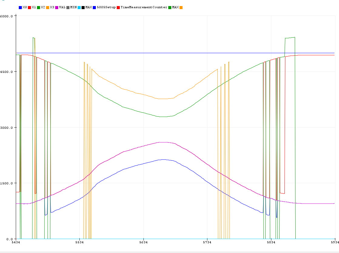
From the outputs: VAL:<val> X1:<T1> X2:<T2> X3:<T3> X4:<T4>
DT: Distance of the peaks in a doublet: DT = <T2>-<T1> = <T4>-<T3>
TM: "Length" of the wire: <T3>=2TM-<T2> or <T4>=2TM-<T1>
Issues:
- DT depends on the coil position.
- TM depends on the length of the sensor.
- No values may be output before locking.
- Ensure good shielding of the lines to the coil.
- If jumps or waves occur, DT or TM may not be set correctly.
Here you can see how the Quartet Analyzer is reconstructing incomplete Quartets. In the middle time range all four signals are present. However the analyzer can reconstruct the VAL-signal (magenta) reliably even if raw signals are missing.
Discussions
Become a Hackaday.io Member
Create an account to leave a comment. Already have an account? Log In.