 Florian B.
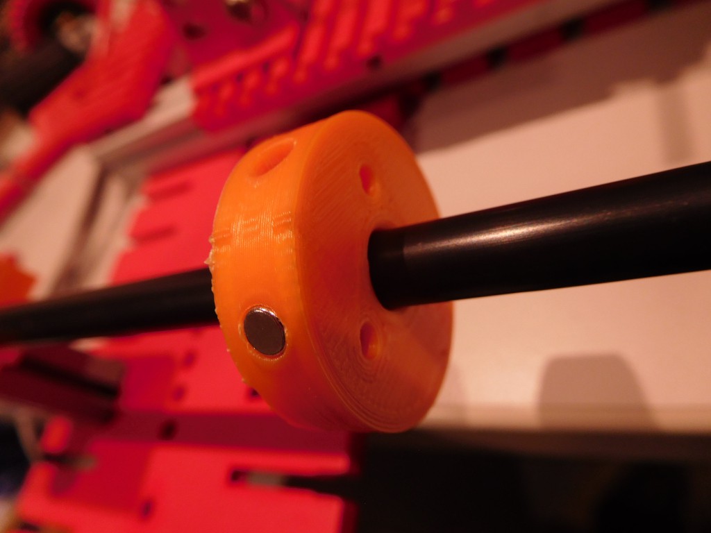
The signal quality depends on several parameters:
Diameter and Material of the Wire
I only checked Ni and NiFe wires. Ni wires seem to work better.
Permanent Magnetization of the wire
Ni wires can be permanently magnetized which can lead to errornous signals.
Especially the region near the reciever coil should be magnetically "clean"
Clampings of the Wire:
Hard clamps generate reflections, soft (rubber) clamps suppresses reflections.
Exciation Voltage
The signal strength depends on the excitation voltage.
Values between 10V and 20V are ok. In my setup higher voltages are not recommended due to the driving CMOS IC.
Duration of Excitation
The longer the signal the higher the signal.
However longer excitations generate mutliple wave trains.
Goal is to have only a "wavelet" with one prominent peak.
Cursor Magnet orientation and strength
stronger magnets can create larger signal amplitudes. But also the orientation of the magnets are relevant.
I achieved best results with Nd-magnets positioned around the tube with magnet poles showing in the same direction namely towards the wire. The pucture above shows the new magnet holder for up to 6 4mm Nd-Magnets.
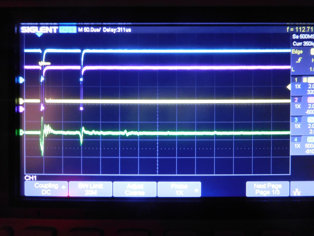
With three magnets loaded and damping at both ends I am getting a very strong and clear single wavelt pulse. The relfection (right) is below the comparator threshold:
Receiver Coil
Number of windings of the reciever coil. The more windings the larger the signal. However with larger number of turns also the direct response of the excitation signal prolongs. I am using 700-800 Windings. But I will check if 1000 Windings will yield a better signal.
Amplifier Circuit
The amplifier is critical. Especially the RC filter between the first and the second Amplifier stage is critical.
Comparator Circuit
Adding small hysteresis by a feedback resistor to the + input will suppress ringing oscillations
Discussions
Become a Hackaday.io Member
Create an account to leave a comment. Already have an account? Log In.