 Andy Geppert
This is the schematic I came up with by referring to various web sources, especially similar SparkFun and Adafruit shields.
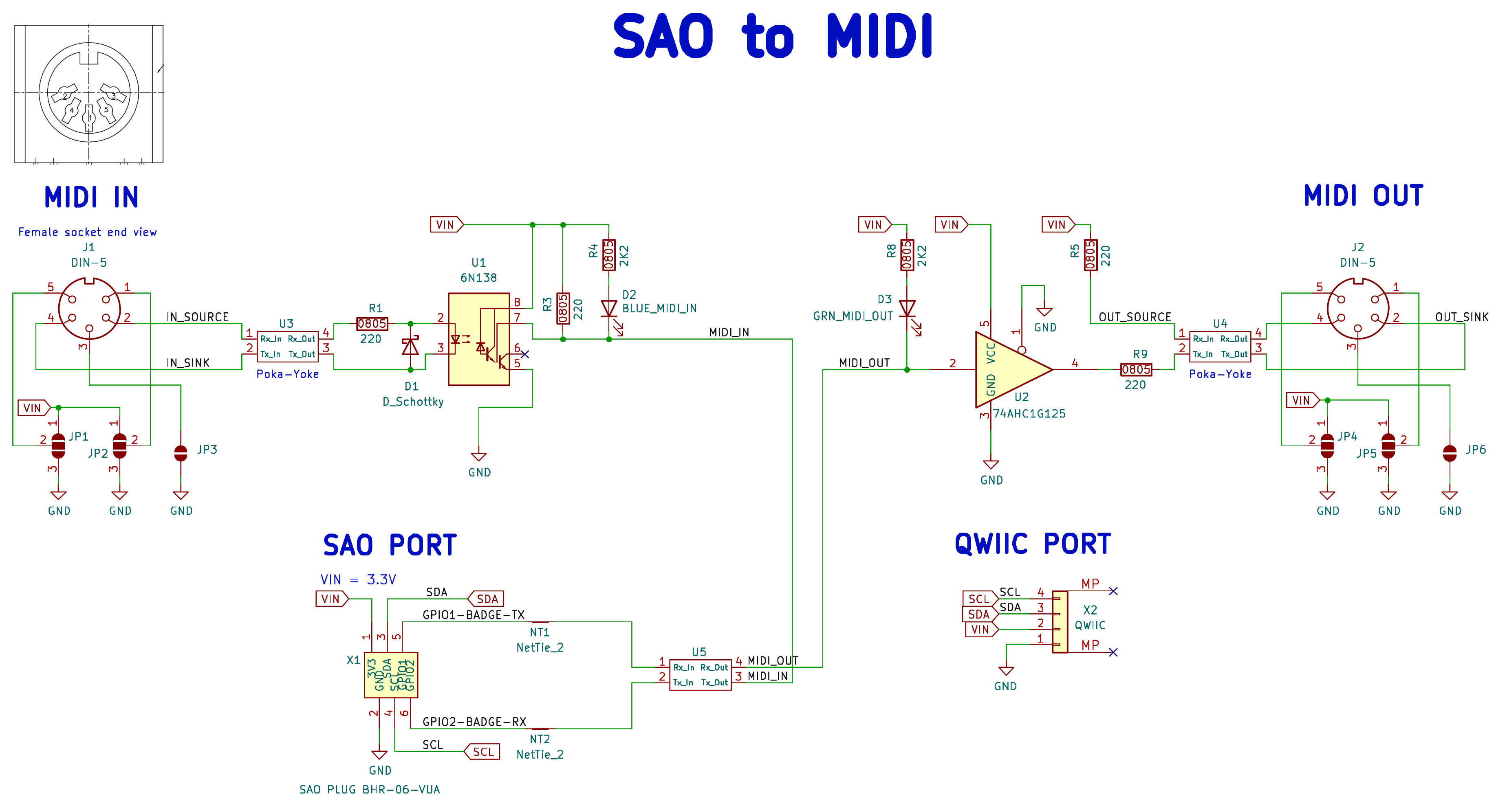
I also include Poka-Yoka resistor pads in case I messed up the polarity of the signals. This was inspired by https://github.com/PabloOyarzo/poka-yoke_rxtx and modified by me to have the correct footprint. It's untested until I get the PCBs!
The layout is fairly simple, in the same form factor as many of my other SAOs. It just barely fits the two MIDI ports side-by-side!
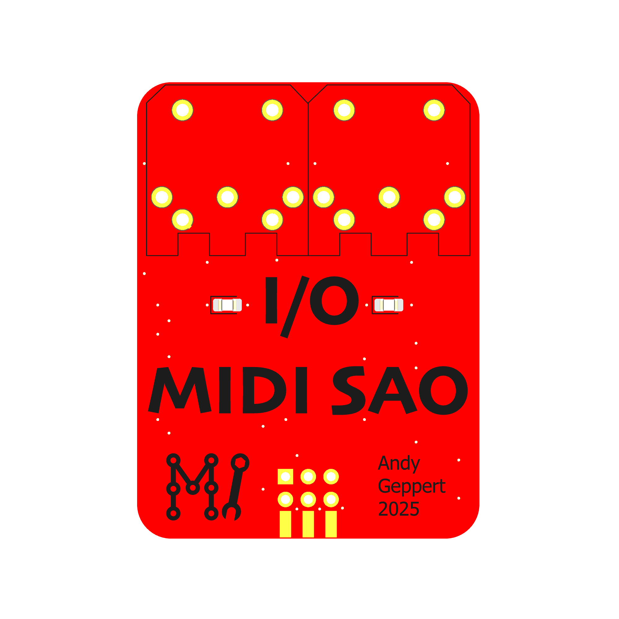
To the left and right of the I/O text are two LEDs to represent data flow, respectively.
All of the other components are on the back side:
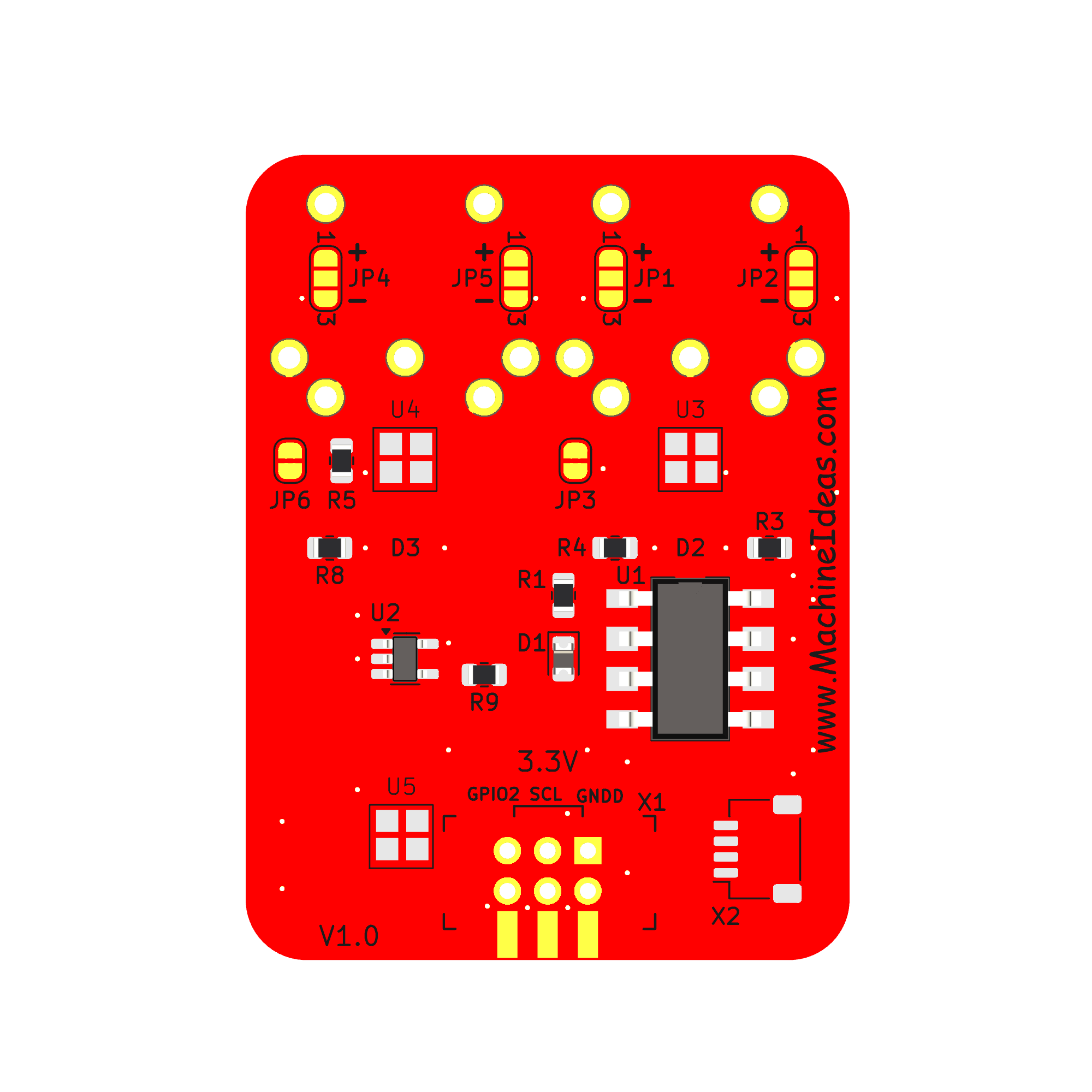
It was an exercise in restraint to keep V1 simple and not add more features!
Discussions
Become a Hackaday.io Member
Create an account to leave a comment. Already have an account? Log In.