 frida moreno
Brief Overview
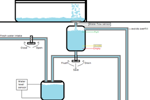
We built an automated paint mixer that allows users to input custom Cyan, Magenta, Yellow, and Black (CMYK) color values (from 0–100%) and automatically dispenses the corresponding color amounts using peristaltic pumps. To maintain cleanliness and prevent clogs in the tubing, we implemented a multi-cycle water flushing system to start after the custom paint has been made and mixed using a magnetic stir plate. A reverse flow mechanism prevents residual paint from interfering with the paint ratios and minimizes paint waste. Currently, an Arduino Nano Every and a 12V batter supply powers the entire setup which is connected to a Macbook running the Arduino IDE commands.
Methodology
Calibrating Flow Rate
We began by connecting a single peristaltic pump to the breadboard to measure its flow rate. This step was essential for calculating the duration each pump needs to run in order to dispense the correct amount of liquid corresponding to the desired color composition.
Initial CAD Design
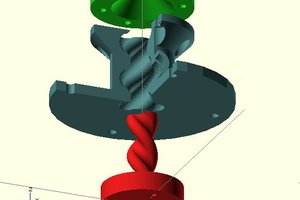
We designed and printed out a very basic CAD design, prioritizing functionality over aesthetics using Fusion360 to make the design and a Bambu Lab X1E 3D printer to bring it to life. The general shape was inspired by Keurig coffee makers, not because we were drinking a lot of coffee at the time, but because we thought the size and shape seemed very optimal for dispensing fluid and keeping the inner workings (the pumps and all) hidden. The design also required two separate prints which was perfect because the printers we used couldn't have held the entire body in one piece anyway.
Some specific features include:
- Space to hold stir plate base
- Hole in the front for knob
- Tiny hole in the back for stir plate wire
- Top container
- Hollow interior to hold 4 pumps
- Space on back for output tubes to enter CMYK bottles
- Space on top of base body for input tubes to exit
- "Color By Code" engraving on front and pump peep hole in front for funsies
- Open top
- Easy access in case of faulty wirings
- We didn't add anything to cover the breadboard and wiring top because (1) it looks cool (2) it's a work in progress so it would be annoying to have to keep opening the top up to access wiring
- Embossed "Color By Code" title was engraved using one of the built-in features of the Bambu Lab printers
Hardware
The two red driver modules are connected to each other and can support two pumps each. The 12V battery supply connects directly into one of the drivers and we mapped out the pinout connections to the code to control the flow directions of each motor. For space purposes, both red driver modules are placed on the breadboard using foam mounting squares.
The two pieces of the CAD design (the body and pump cover) are super glued together.
Each of the peristaltic pumps has additional tubing attached to each of the ends to extend the flow. The peristaltic pumps themselves are faced mirroring each other -- two face one direction and the other two face the opposite direction (see gallery image).
Software
All of the code was written and executed on Arduino IDE. To start, the code prompts for user input of CMYK values, then the specified amounts are dispensed into the output cup (currently based on the flow rate). Any leftover paint in the tubing is returned to the original paint containers by reversing the pump directions. Once this is done, there is a brief delay while we get ready for the flushing mechanism (swapping around cups). Then there are 5 cycles of water flushing before the program terminates.
Testing
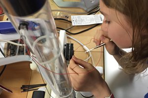
To test the code initially, we used water and food coloring. This was a cheaper and neater alternative to wasting a lot of acrylic paint just to make sure the pumps were flowing in the proper direction (See gallery image).
Future Work
- Bluetooth App
- Replacing current microcontroller with one compatible with bluetooth
- Making a mobile app that has a color grid so that people can pick CMYK colors from there
- Paint Colors
- For the final...
 doctek
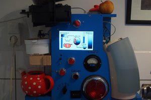
 leandro