 Vedran
I've recently gotten into making PCBs at home and with that, came the need of mounting SMD components. Sure, I could suck it up and just hand solder those 5 boards a year I will probably be making, but where's the fun in that? Instead, I wanted to get a hotplate to make the job easier.
Looking at the commercial ones, they are great, but not something I can justify purchasing considering the low volume I'm running with. However, internet offers a couple of pretty nice DIY solutions. Just here on hacakday, there's some really nice projects I got inspired by:
- https://hackaday.io/project/194305-diy-usb-pd-powered-mch-automatic-reflow-hotplate
- https://hackaday.io/project/194863-makeshift-reflow-hotplate
- https://hackaday.io/project/181170-reflow-pcb-hotplate
- https://hackaday.io/project/178336-open-reflow
But as is the nature of DIY, you start with something someone else has done, and take it your way to accommodate your needs and most importantly, the parts you have available. So without any further ado, this is my version of the DIY hotplate.
Specification
- Wide input voltage 12V - 24V
- Heating power of 50W - 70W (depending on input voltage)
- max plate temperature: 200 ºC (tested so far with 19V input)
- Heat up time: TBD
Design
Heater
I wanna start the design with the centerpiece of this device, namely the heating element. There's a lot of good way to make a decent heater for a hotplate and I probably picked the worst one - an FR4 PCB, whose top layer has been routed into a long wire acting like a heater. But the reasoning for this decision is simple - the design works for lower temperatures where I intend to operate, and I have the capabilities to make PCBs at home, which means no extra parts needed. But I do expect it to fail at some point and have some ideas for improvements - but more on that in the project logs. Here, we talk the build :)
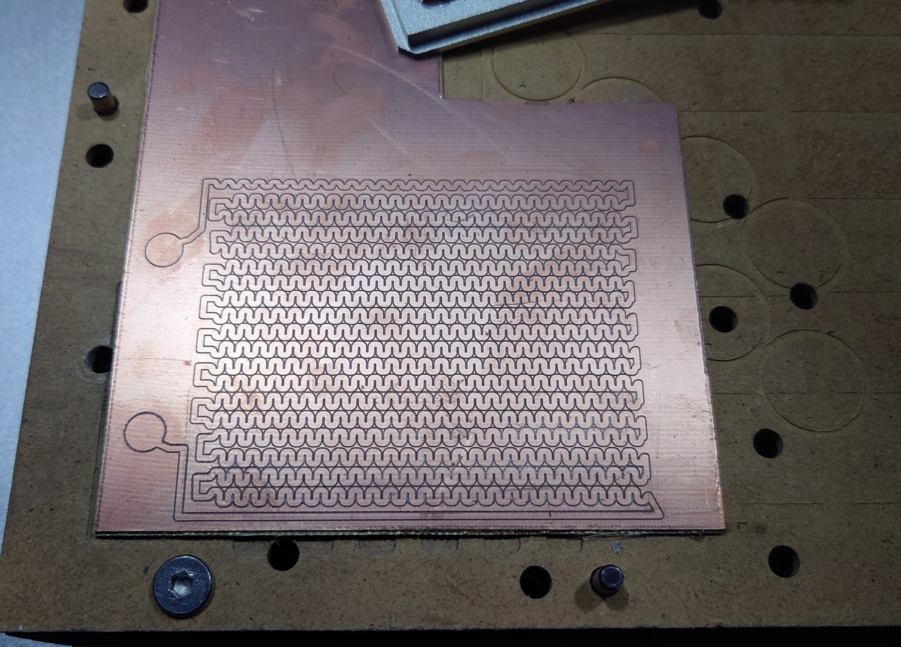 | 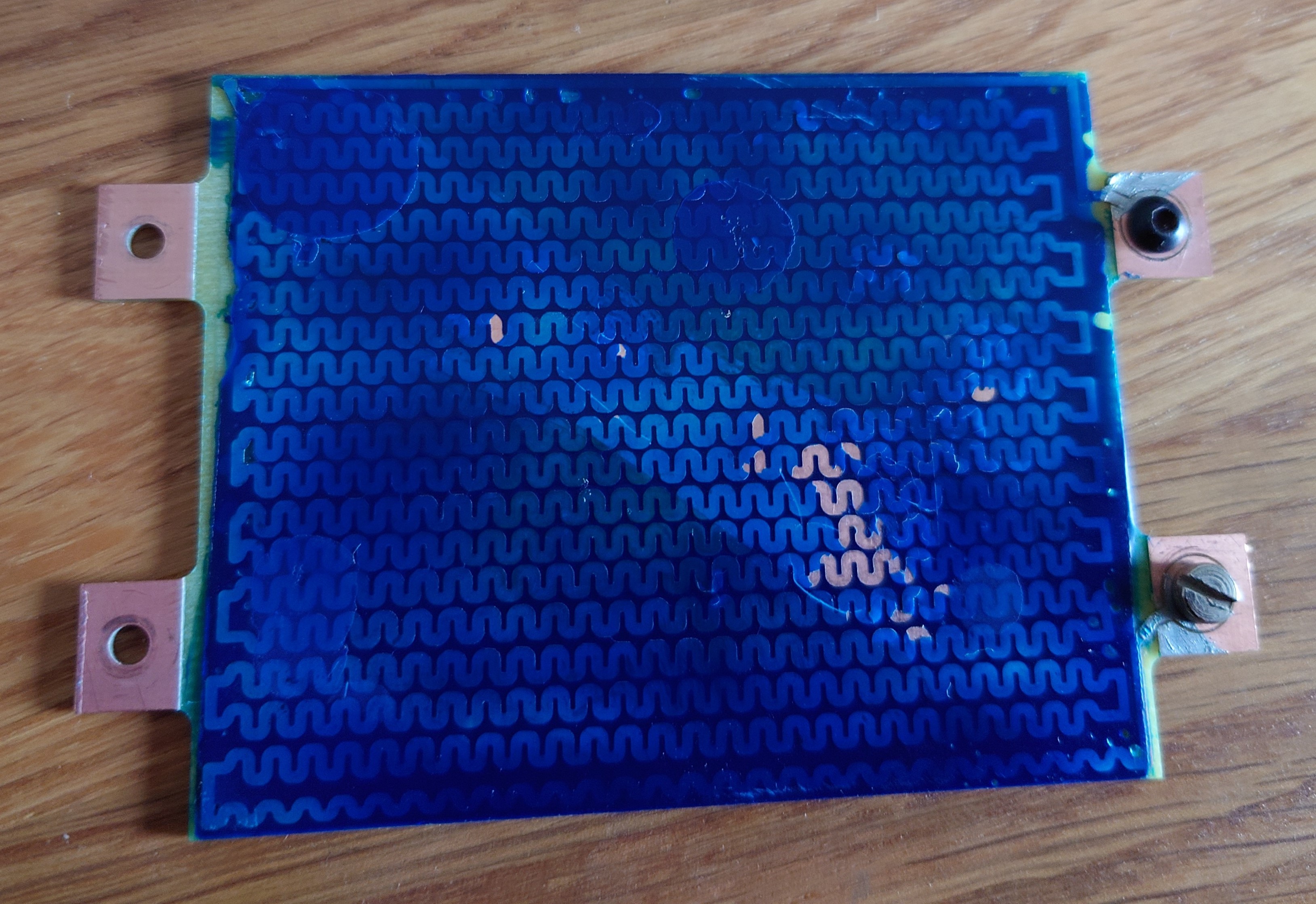 |
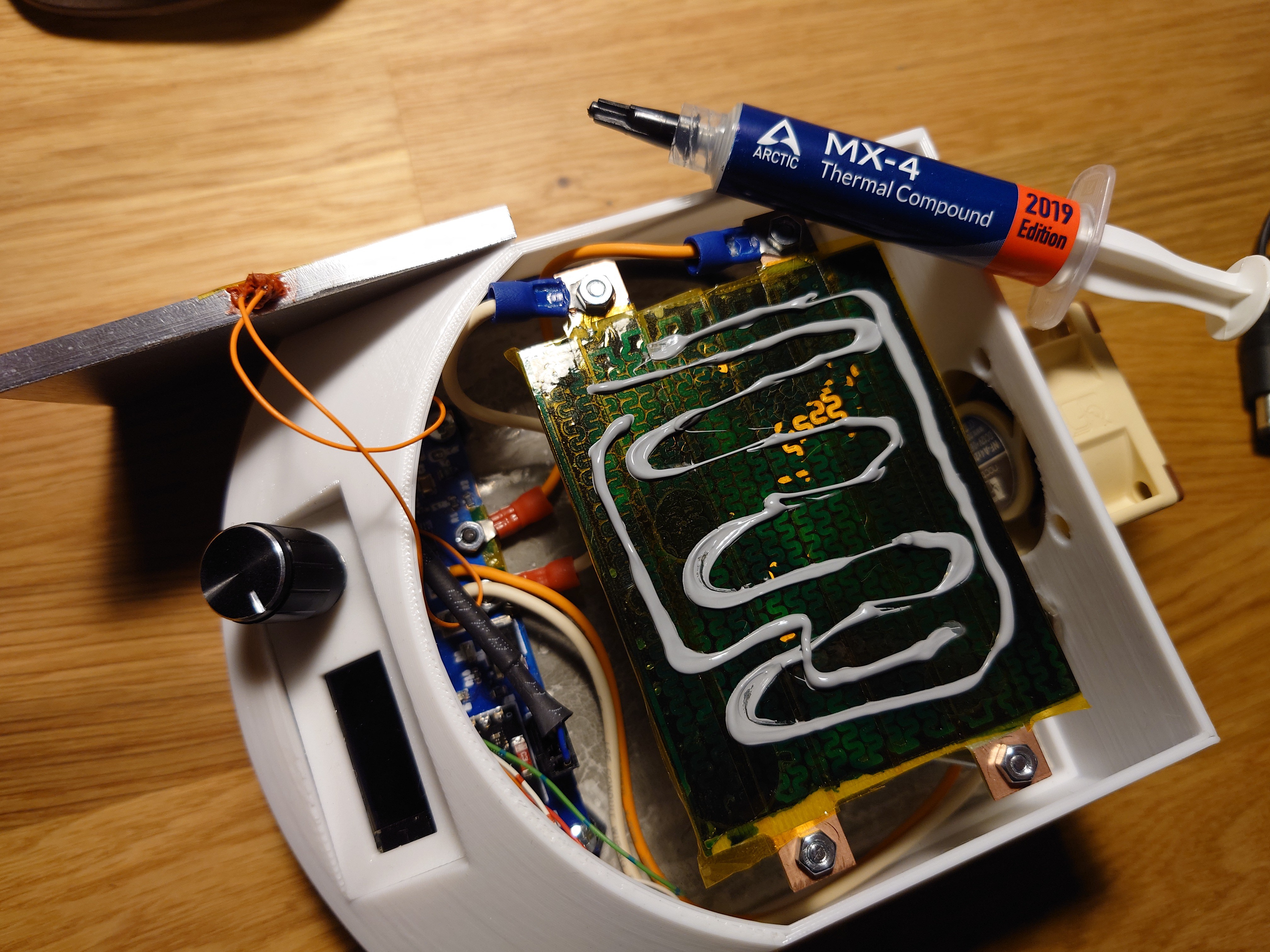
I went through the trouble of coating the board with soldermask, but that turned out to be a waste. Few heating cycles later, the soldermask started to chip off. To be on the safe side, the board got a layer of kapton tape before assembly to aid the electrical insulation. To help distribute the heat more evenly, I slapped a slab of aluminum on top of the heater - right after applying a nice coat of thermal paste. The thermal past specifies continuous use temperature of 150ºC so I'm curious to see long term effect.
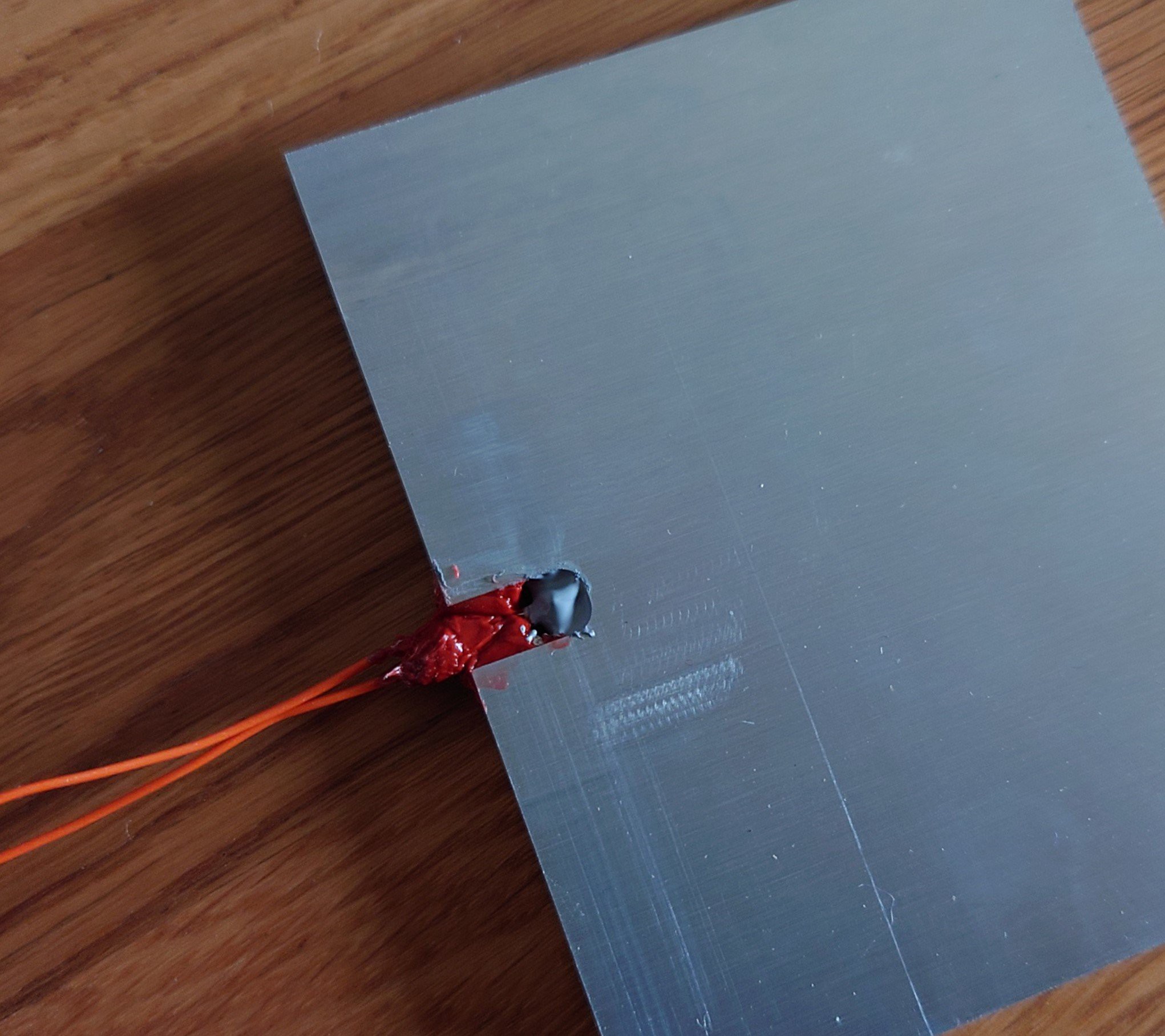
Aluminum plate is milled from a 5mm plate with a small slot for a PT100 temperature sensor, and the temperature sensor is fixed with the help of some high-temperature silicon, while the tip of the sensor is brought in contact with the aluminum, and the whole connection again bathed in thermal paste.
Electronics
Electronic design started pretty simple, but then a couple of "fun" features snaked in as well. Both the schematic and kicad project can be found in the github repository attached to this project. But to give a short overview, there's a 5V buck converter built around RT6200 (using the reference schematic), connectors for OLED screen and rotary push button, no big surprises there. But then I went with Wheatstone bridge for PT100 for which I thought it would be fun to have a 3V zener voltage reference for no particular reason except that I've never done it before and really wanted to try it out. (Well, actually I hoped it would be more stable than 3.3V power supply to feed the bridge)

On the list of "definitely unnecessary" is an INA250-based current monitor, measuring just how much power is consumed by the heater. But I had one lying around, so why not?

To drive the heater, I picked a simple recommendation from a friend of mine. I opted to not use a gate driver circuit, mostly because I wanted to keep things simple and could live with having a very low PWM frequency of sub-1Hz to drive the FET.

Oh, and there's also a connector for a fan, because I thought it would help with the temperature of internals to have a fan blow some air in. It might also help cool down the plate faster after use. It's intended to run PC fans, taking in power and PWM signal. But I'm not sure how useful that will be.
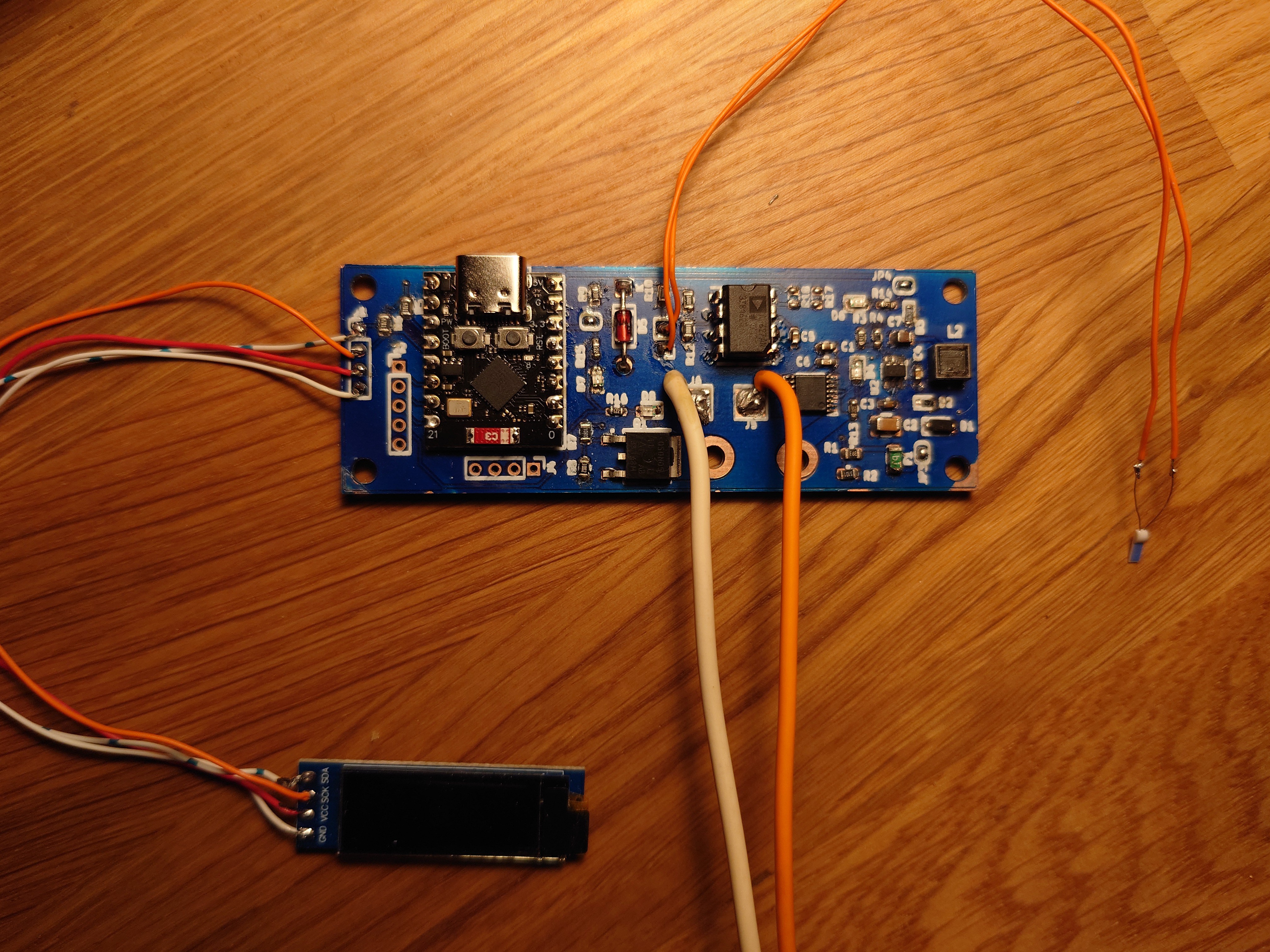
All this then came together on a nice little PCB that could be baked on this half-finished hot plate.
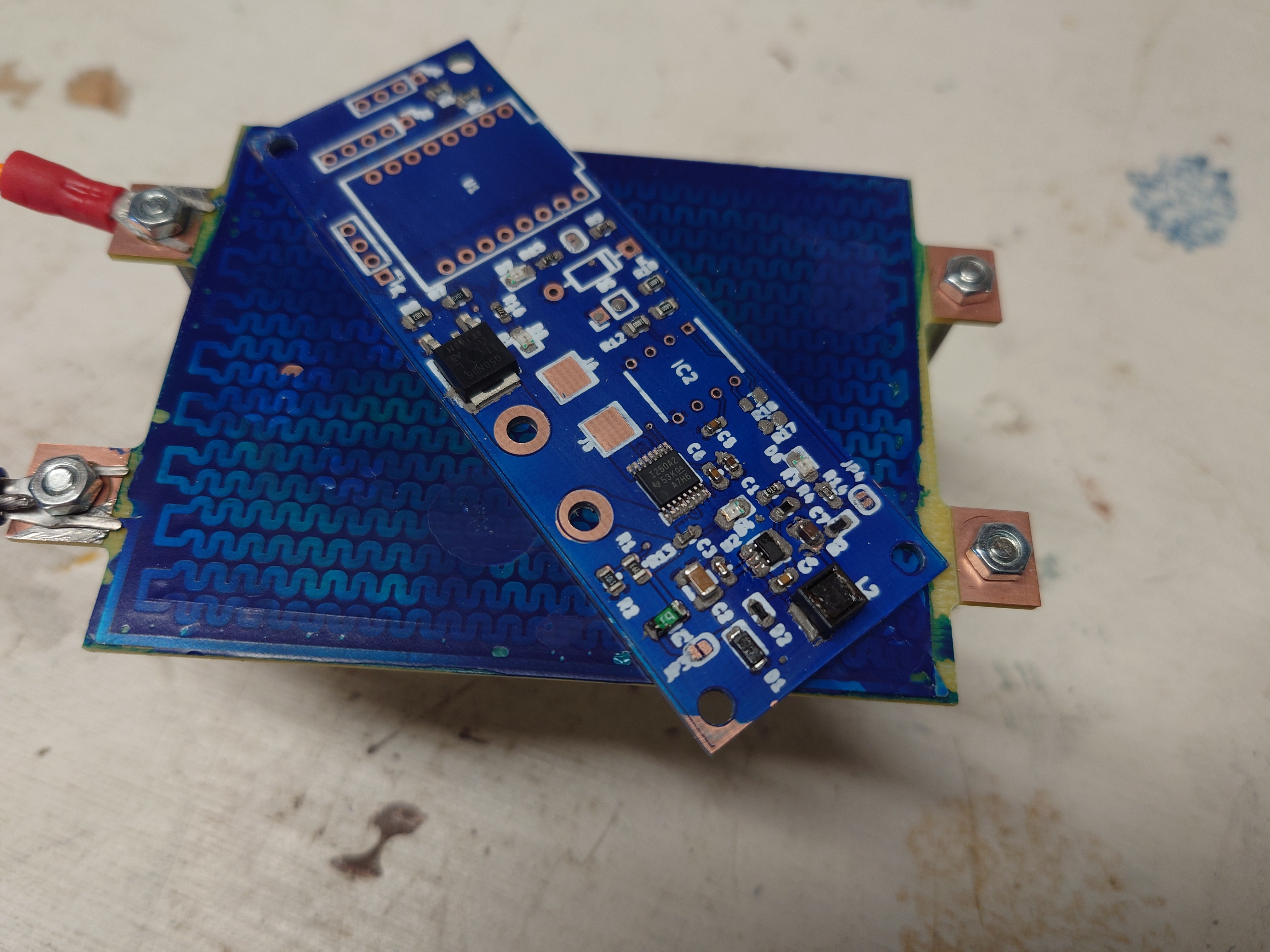
Finally, there's something to test with all the peripherals attached.
Casing
Casing for a project is the part I usually overlook the most and end up spending most of the time on. In part because I would like it to look and feel nice, but in part probably because I just don't have enough experience with designing housings (I'm a firmware guy by trade).
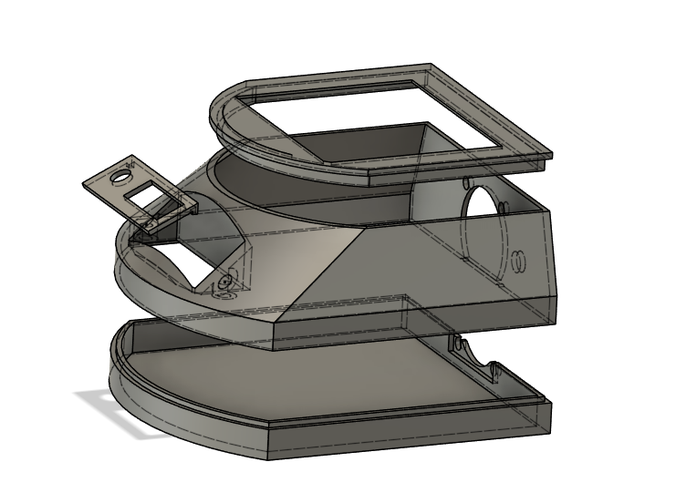
I went for a modular design, where the main case is split in half, for ease of assembly and printing. There is also a cap on top which is printed separately to match the placing of the heating element which doesn't have a strict placing position.
The mounting plate for HMI is also a separate component so that it's possible to play with angle of the plate, and distance to the electronics underneath. Namely, to place the PCB as far away from the heat, it resides right under the HMI section.
Firmware
Current version of the firmware can drive the heater to a fixed setpoint and preview some data like voltage and current input, plate temperature and internal temperature (via built-in temperature sensor in ESP32). The user interacts via "gestures" deducted from the rotary encoder:
- Button single press: Enter/exit setpoint mode
- Button long press: Start/stop heating
- Button double press: Change active screen (change between "Manual mode" and "Statistics")
However, since I truly enjoy programming, I really want to have fun with this. So I'll be replacing current screen concept with "applications". Where each app will be rendered as a separate screen, will be able to keep internal states and control the hardware. So current "Manual mode" will be an app for manually controlling the heater. Similarly with "Statistics", it will be a stateless app that simply displays system stats.
I also want to add an app for following a reflow profile, where a user can program in a profile for e.g. Sn42/Bi58 solder paste, and the hotplate will automatically execute the profile.
Finally, I want to incorporate a timer functionality, so that it's possible to have a user-controllable timer in "manual" mode, and an automatic timer in "profile" mode.