 Vedran
What?
Before digging into a project, it's worth thinking about what this thing is and its basic building blocks. What does a hotplate as a product need to do its thing?
Well, the centerpiece is the heater, a resistive heating element. As the name implies, it's a relatively short piece of wire with low resistance that gets heated up as the current pass through.
Something then needs to supply the current to it. And something else switch the current on and off to control when we're heating and when cooling. This in principle is a working hotplate, you plug the power, turn the switch on and it heats up. Looking at when the solder paste on top of it melts is enough to know when to cut the power. (yes, yes there are heating profiles, but for the most parts...)
However, we can get more fancy and add a temperature sensor to get real-time temperature feedback. If a smart device, say a microcontroller, reads that sensors and and can control the switch, we get a closed loop temperature-controlled hot plate. So fancy.
At this point, we have a temperature controlled heat plate but who decides to what temperature it should heat up and when? Well, the user. And users are often demanding in a way that they need some sort of interface because they simply refuse to flash in a new firmware every time they require a new setpoint, duh! :D
Okay, a user interface. But what does that entail? If we agree that the main user of this device is a human, we would need a way for it to input the temperature, and get a feedback on the current state of the device (e.g. heating, cooling, temperature reached ...).
Finally, all of this should, ideally, be placed in some kind of casing to hide the wires and electronics and make it easily portable.
How?
With the basic building blocks in place, it's time to connect them. The overall design is outlined on the picture below
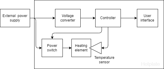
To feed the device, I opted out for an external power supply with barrel jack connector and for better flexibility went with wide voltage range (12V - 24V).
I recently started plying with some ESP32-C3 superminis and they seemed perfect for this project - so I picked them as a controller for this project. This then mandates a step-down voltage converter from any supported input to at least 5V.
Temperature sensing can be done in many ways, and I went with a slightly unusual choice for hobby projects, a PT100 sensors, increasing its resistance with temperature. I did that instead of something like LM35 purely to support the full operating range of this device. While LM35 cannot go higher than 150C, PT100 can easily go over 300C - way past what this hotplate
To read the temperature sensors, I considered both a simple voltage divider and a wheatstone bridge. Ended up with slightly complicated whatstone bridge but it gets the job done.
As for the user interface, I initially considered a small OLED and 2 push buttons, but eventually settled on OLED screen and a rotary encoder with built in push button - I absolutely love those. They help create (in my opinion) a very intuitive interface while being only a mild pain in the ass to work with from the firmware point of view.
And finally, for the casing, I settled on 3D printed case with some sleek lines. I split it into 3 parts for easier printing and component mounting.
Discussions
Become a Hackaday.io Member
Create an account to leave a comment. Already have an account? Log In.