 fcipaq
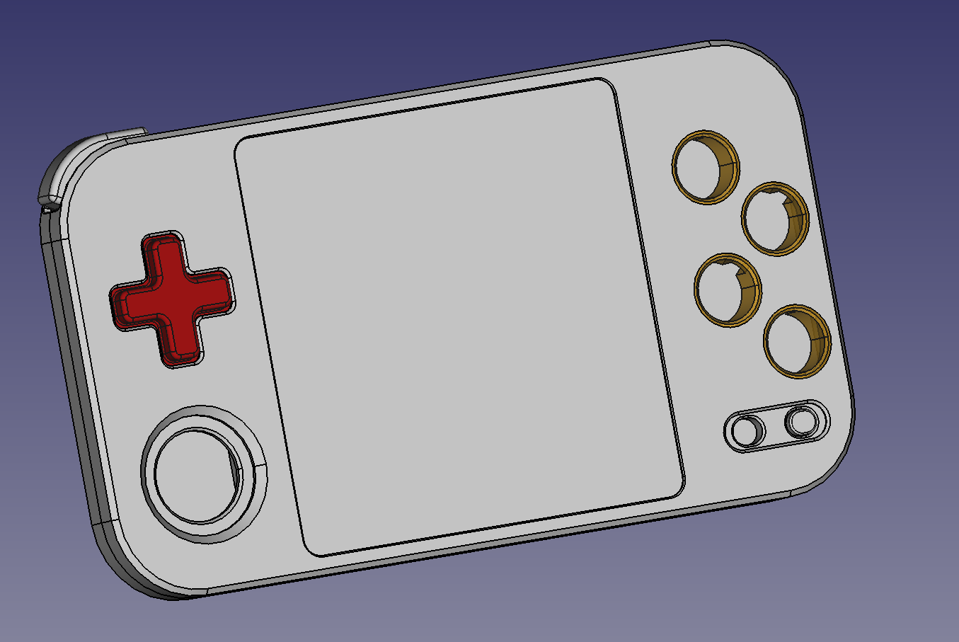
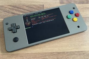
After the Pico Held was completed, I tried to improve the design and I worked on what was criticized: The missing shoulder buttons, the missing DPAD and the low res display. I managed to decrease the thickness to 10 mm and I was able to improve the buttons in comparison to the Pico Held XL, which suffered from scuffed buttons which scratched against the aluminum case.

With the RPi Zero model - since an additional microcontroller was needed to manage the buttons etc. - there was no room left for a DPAD and I instead opted for a hall effect analog stick (from the Switch). While this is great in games like Mario Kart, it's sub-par for classic retro platformers and lacks the precision of a DPAD. The DPAD is really hard to get right. I'm currently at revision 6 or so... But I think in a retro handheld, it's an absolutely crucial part. I find it pretty hard to design it so that it doesn't have too much friction when scratching against the metal case.
The sound output is via an I2S amp, which this is definitely an improvement over the PWM sound of the original Pico Held and the Bluetooth sound of the Pico Held XL.
The screen is a 720 x 720 4-inch display. And that's pretty hi res (especially for a microcontroller). The RPi Zero and RP2040 will feature a parallel "DPI" display, while the ESP32-P4 has a MIPI-DSI display. Unfortunately, on the RPi Zero there is a reduction in color resolution because the DPI display and the I2S output share some GPIOs. In my opinion, the 720x720 is pretty perfect for SNES integer scaling by a factor of 3 (with only cutting off 8 pixel on each side and almost filling up the entire screen vertically, though that's squre pixels of course). I was able to get a SNES emulator running at a decent speed on the ESP32-P4.
On the RPi Zero model, a microcontoller initialized the LCD via SPI and also takes care of LCD brightness, amplifier enabling, ADC sampling, button control as well as battery/charge monitoring. I started out with a classic 4-layer PCB (compinents & signals, GND, power, signals).
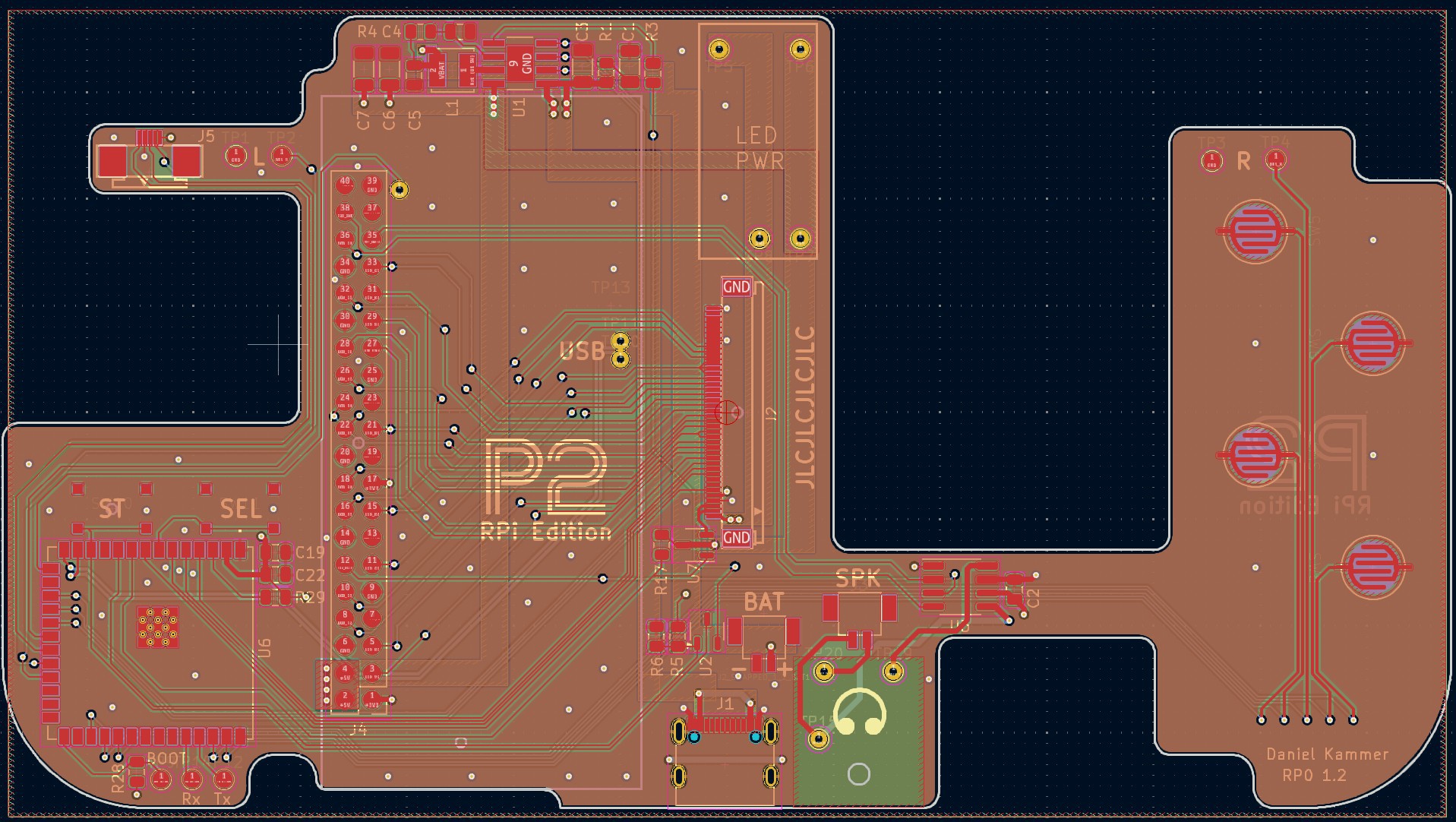
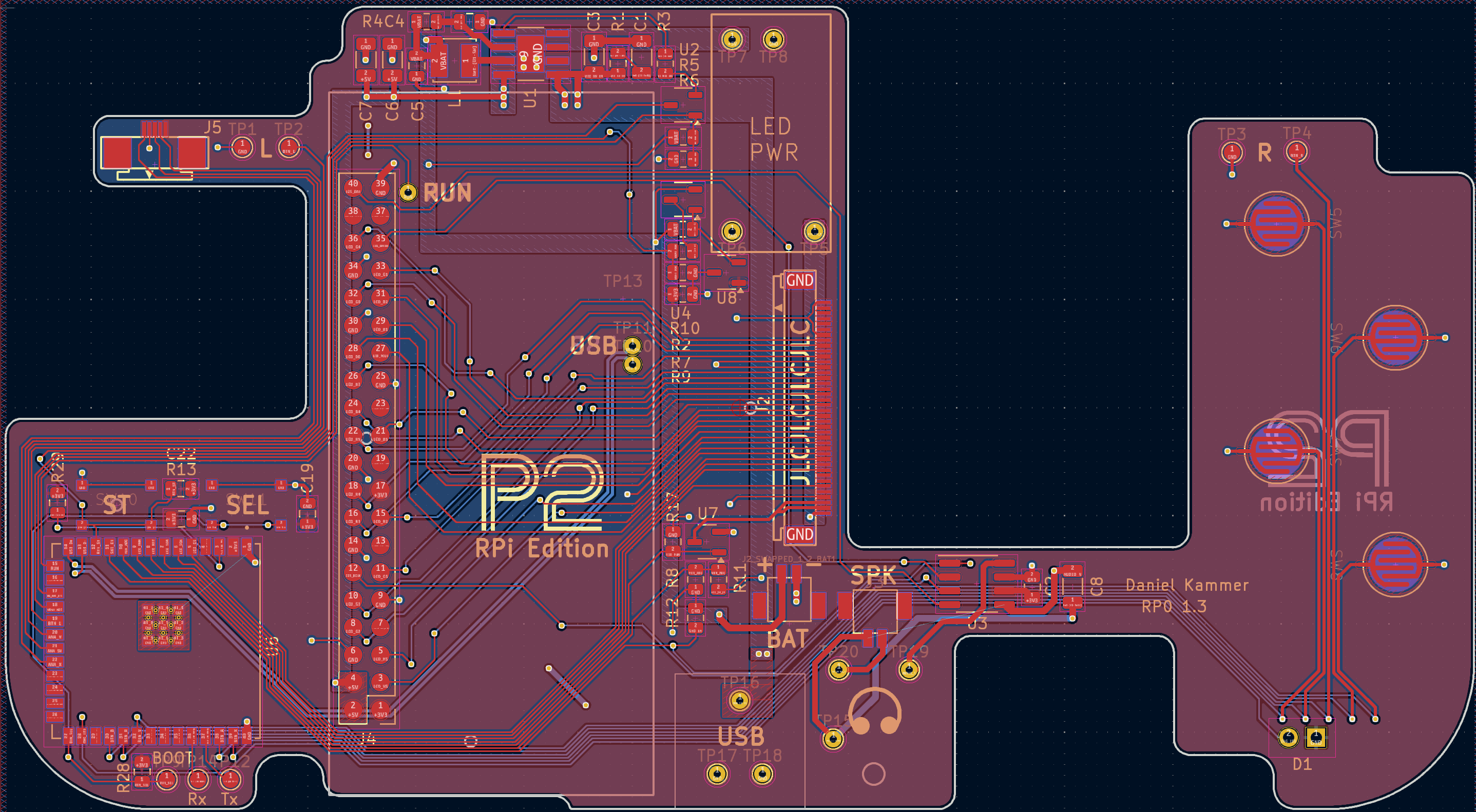
But then, on the next revision, tried doing a 2-layer PCB (for cost reasons) - and guess what, it works reliably :) (Pixel clock is less than 40 MHz). Sound is not too noisy as well.
Because the enclosure is CNC-machined, all I/Os have to be centered between the top and bottom shells, making is necessary to use "carrier boards" for the USB socket and the audio socket (in order to get their height right).

Battery life is expected to be rather short on the RPi Zero device, but will be a lot better on the microcontroller devices. To be honst, I don't really prefer the RPi Zero in my projects - while it's certainly an amazing piece of hardware, it's usually too bloated for the kind of projects I do. I like that you can flip a switch on a microcontroller and the device is ready to go.
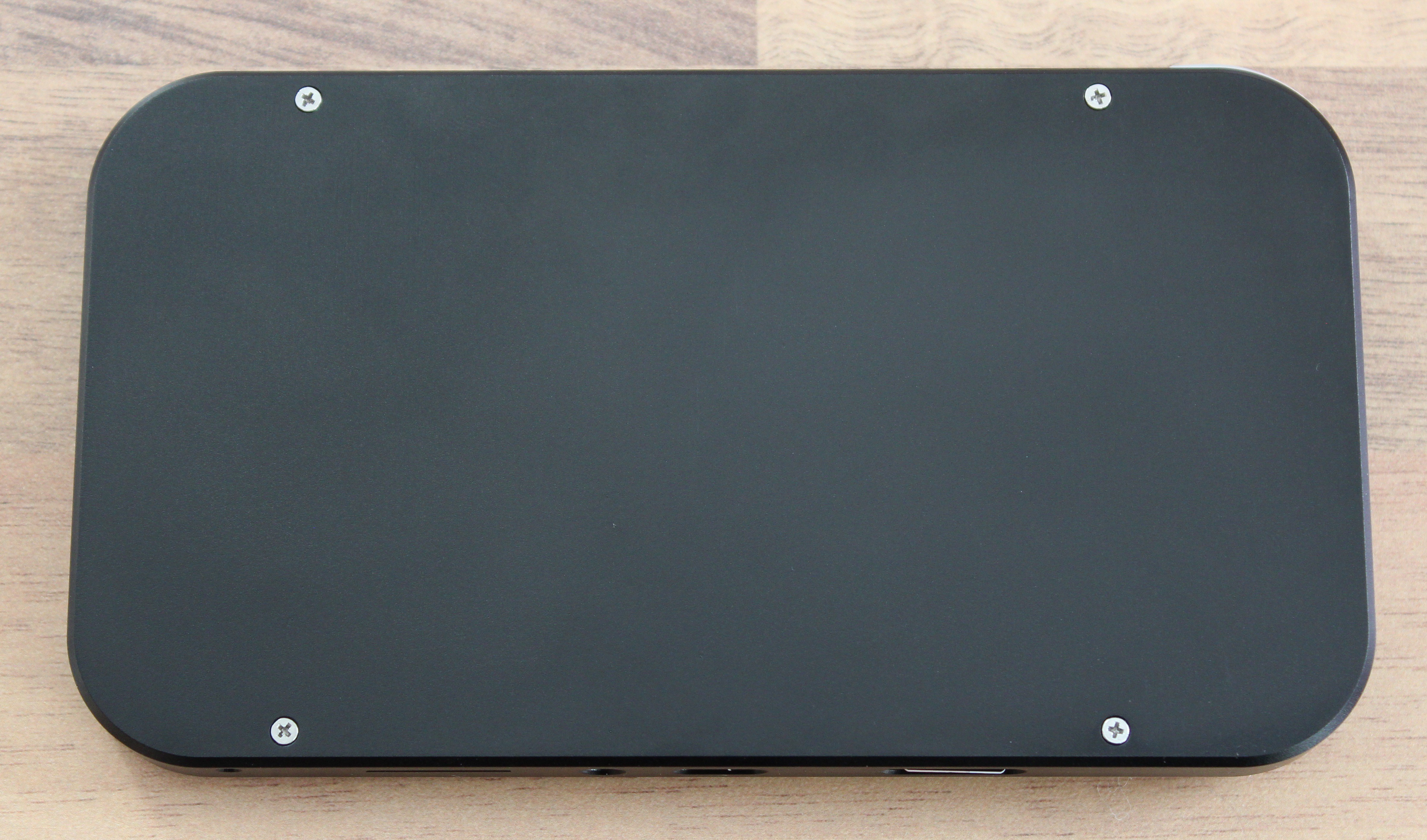
The back still looks a little empty - any suggestions are welcome :)
I hope you found this interesting and stay tuned for more :)
 Arnov Sharma
 Michael Gardi
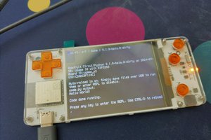
 deʃhipu