 Cliffweb03
This Amrel PPS-2322 suffered failure of both channels sometime prior to my acquisition. I purchased this because the front panel display and keypad operated without issue, in spite of the loss of both channels. On opening the unit, the 39 ohm R142 and R155 were clearly burnt, and upon removing the board to desolder these and inspect the power transistors I found that there were a total of ten components failed symmetrically on each channel. Several power resistors were unidentifiable due to the heat changing the color of the coding bands. Fortunately, blogger Kerry Wong posted detailed photos of his teardown of a functioning unit, from which I determined the values for those resistors.
I’ve listed the replacements in the below table.
| Common Part # | Description | PCB Reference |
| TIP31CG | TRANS NPN 100V 3A TO-220 | Q29, Q21 |
| TIP32CG | TRANS PNP 100V 3A TO-220 | Q26, Q41 |
| MOS5C271J | RESISTOR | R143, 151 |
| ROX3SJ1R0 | RES 1 OHM 5% 3W AXIAL | R145, R159, R152, R162 |
| 2N3904TFR | TRANS NPN 40V 0.2A TO-92-3 | Q35, 36, 38, 47 |
| ROX2SJ1K0 | RES 1K OHM 5% 2W AXIAL | R146, R104 |
| ROX2SJ2R2 | RES 2.2 OHM 5% 2W AXIAL | R119, R154 |
| ROX05SJ39R | RES 39 OHM 5% 1/2W AXIAL | R142, R155 |
| 2SD1047 | TRANS NPN 140V 12A TO-3P | Q37, Q39, Q44, Q45 |
| PR03000203600JAC00 | RES 360 OHM 5% 3W AXIAL | R141, R153 |
Installing these replacement components brought the unit to a state where it was outputting a positive voltage on both channels, but the setpoint and the actual output voltage differed greatly (~9 V observed intermittently with an external DVM with a 0 V setpoint). Additionally, over current was triggering on both channels, even with no load connected.
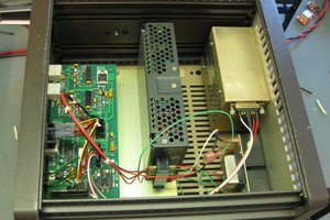
Several unproductive paths were explored at this point (since there are no full schematics available for the unit). I checked D32 and D34 due to minor discoloration of the adjacent PCB, but these were fine (de-soldering and testing determined these are 17 V Zener diodes, size is 1/4 W class, and evidentially should be upgraded). Pulled and checked all the op-amps and comparators to no avail. Frustrated and ready to drop the project straight-in-the-bin I kept checking components and voltages in the hope something would present itself. Eventually I realized that I was seeing intermittent errors and warning beeps every time I disturbed the computer board slotted into the analog board, and concluded that there must be intermittent contact at the edge connector.
I pulled the computer board, gave its contacts an isopropyl alcohol cleaning (99% pharmacy grade) and when I noted that there was still something a bit ‘off’ with the appearance of the edge connector contacts I gave it a few light swipes with 1500 grit sandpaper then re-cleaned it. I also lightly brushed the contacts of the edge connector slot on the analog board with the 1500 grit, checked pin tension, then reassembled. No faults were observed. Though the voltage output still differed grossly from the set point, I could set different voltages and see a repeatable change in the output. Apparently, the unit had lost its calibration setpoints.
The operator's manual is available from a few sites online and copied as an attachment below. Calibration procedures from the manual will require a DVM and a 0.1 ohm power resistor (a 1 % tolerance was sufficient for my purposes). When an operator starts the calibration procedure, the operator should be prepared to carry it through to completion, though one can exit out by power cycling the unit. If one enters grossly incorrect values by mistake (connecting the DVM or load to the wrong channel at the wrong time and reading an incorrect value) then the unit enters into an error state. This is annoying as the buzzer will emit a constant tone and the operator has to keep canceling warnings while again navigating the calibration procedure. But, once calibrated, the unit should now output voltage and current close to the setpoint.
Once the unit is working consider replacing the fan (which in my case was likely to blame for the cascade of component...
Read more »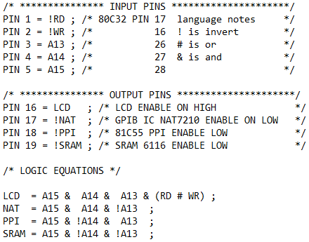
 Quinn
Quinn
 Nick Sayer
 Bharbour
 Alan
Alan