mircemk
At Solid State Tesla Cioils in the case of incorrect assembly, incorrect calculations, or even incorrect wiring of printed circuits, field-effect transistors quickly fail, sometimes with explosions, which also entails financial difficulties, because powerful transistors cost a lot. VTTC have a much simpler circuit, based on one powerful Vacuum Tube, as in this particular case GU50 which is also much more resistant to construction errors.
As mentioned above, the circuit of such a design is quite simple, but, nevertheless, for construction it requires certain skills in electronics and working with high voltage.
This project is sponsored by PCBWay. They has all the services you need to create your project at the best price, whether is a scool project, or complex professional project. On PCBWayyou can share your experiences, or get inspiration for your next project. They also provide completed Surface mount SMT PCB assemblY service at a best price, and ISO9001 quality control. Visit pcbway.com for more services.

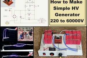
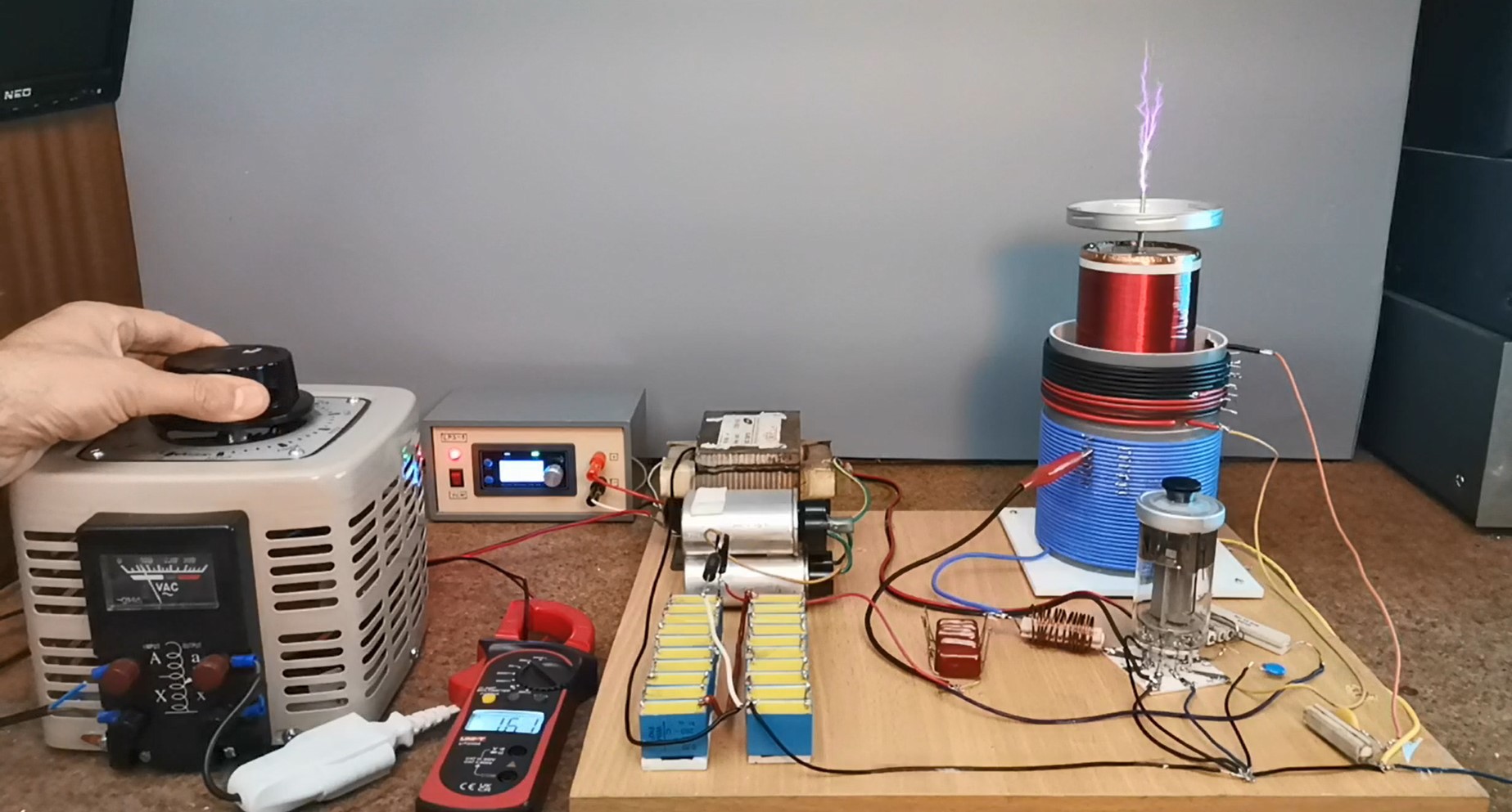
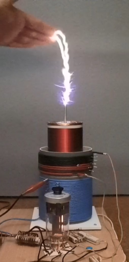
- The power supply section is from a previous project and consists of a microwave oven transformer with a voltage doubler half wave rectifier. For these reasons, a Variac autotransformer is connected to the input of the MOT so that we can control the tube's anode voltage to a certain safe level.
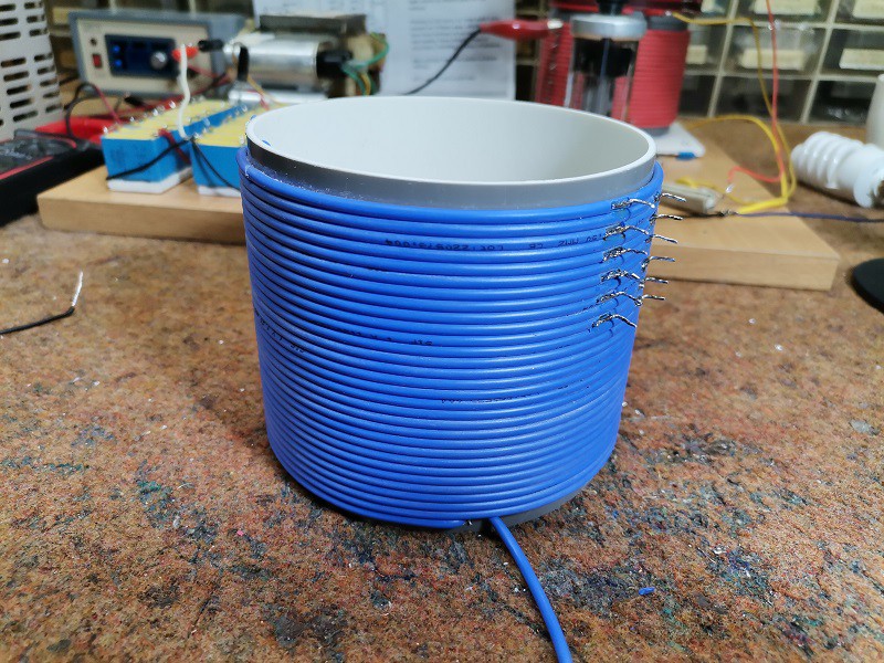
- The primary winding consists of 30 turns of insulated copper wire with a diameter of 1.5 mm, wound on a plastic tube with a diameter of 11 cm. After the twentieth winding, it is desirable to make a tap of each subsequent one, for the sake of easier tuning.
- The secondary coil consists of 1300 turns of thin varnished wire with a diameter of 0.14mm. It is wound on a plastic tube with a diameter of 7 cm and a height of 20 cm.

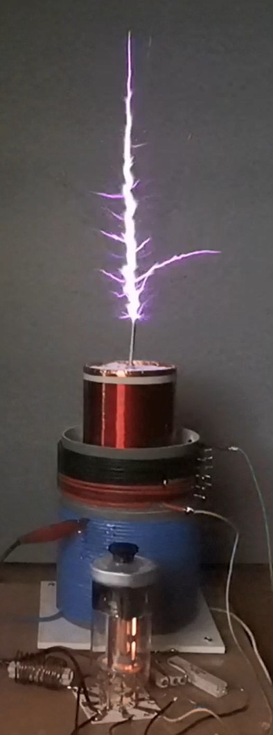
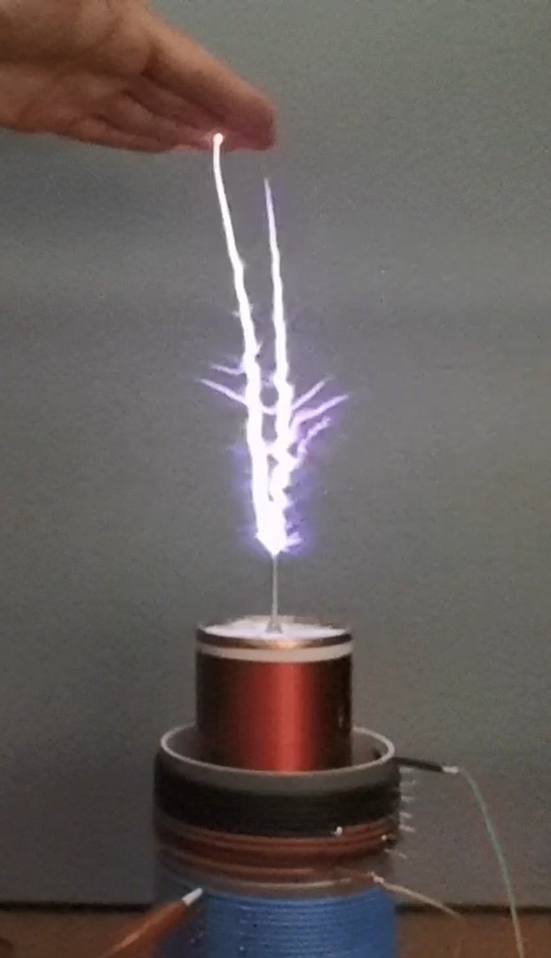
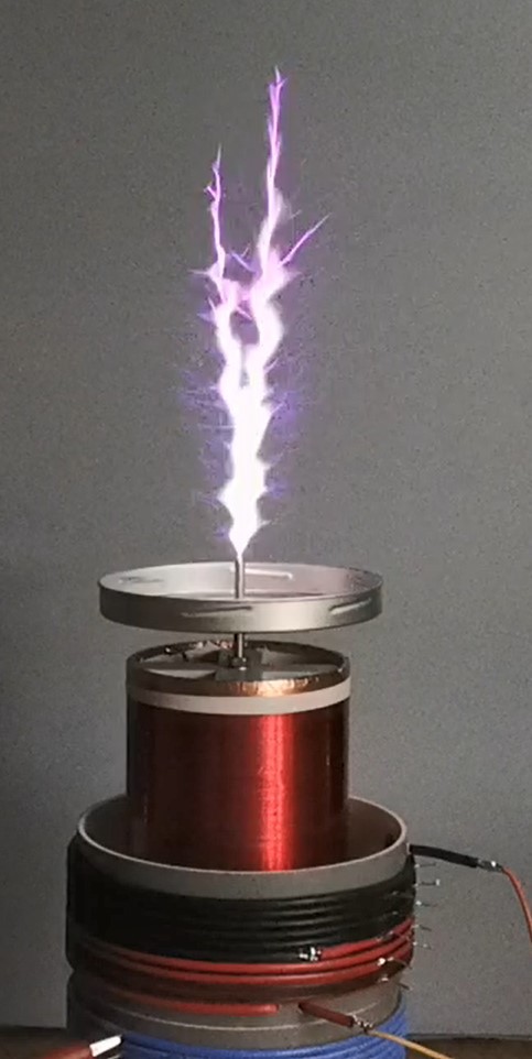
- An aluminum disc or toroid is placed on top of the secondary coil.
- In addition to the primary coil, there is the feedback coil, which contains 10 turns and has taps on each turn for easier tuning.

- It is also worth mentioning such an important detail of the circuit as capacitor C2 - this capacitor is selected individually to achieve resonance. It is quite easy to see the resonance - a small discharge will appear at the top of the terminal even at low supply voltage. With a further increase or decrease in capacitance, the frequency will change, and accordingly, the resonance will disappear. The capacitor must be designed for high voltage.
- The tube heater is powered by an external 12V/0.6 Ampere power supply.
Now let's see how the device works in real conditions. With an approximate value of the capacitor and a certain number of windings, usually about 25, we first bring a low voltage to the primary of the MOT, and we bring a compact fluorescent lamp close to the Tesla Transformer.
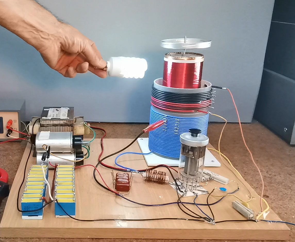
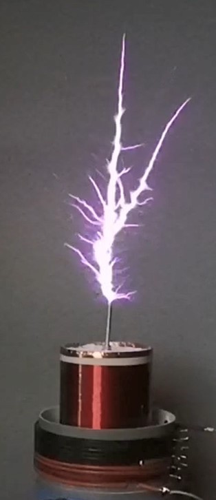
If the lamp lights up, it means that the circuit is well connected, otherwise we should check all the wires, and if they are well connected we should rotate the wires from the primary coil. After that comes tuning to get the biggest spark. We increase the voltage with the variac until a small spark with a length of 1-2 cm appears. Then by gradually changing the number of coils from the primary and the feedback coil we try to get the longest spark. When we achieve this, we still have to increase the input voltage with the variac to some safe level. GU 50 can withstand pulse voltage up to 8 thousand volts. If we notice that the anode of the tube becomes a red heated color, it is a sign that it is overloaded and we need to reduce the voltage.
And finally a short conclusion. The process of making Tesla coils requires patience and diligence, so if the device does not work the first time, you need to look for the reason and figure it out, but not give up.
This is a great simple Tesla Coil design made with only one Vacuum Tube and a few passive elements, which has a number of advantages over similar transistor devices. Despite...