 Tony Francis
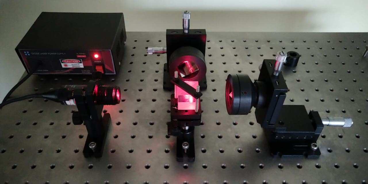
The initial setup for our Michelson interferometer is complete. We've chosen to use retroreflector mirrors for the setup, a design choice critical for both Fourier Transform Infrared (FTIR) spectroscopy and our current visible-light testing.
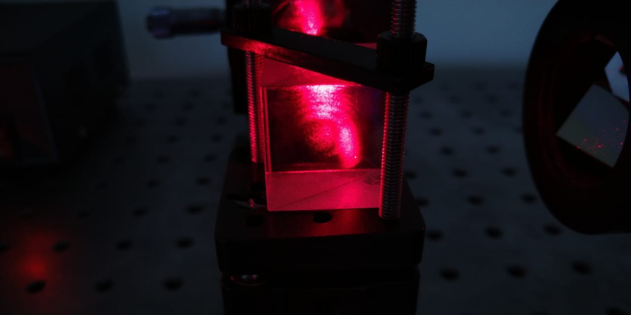
In our setup, the two retroreflector mirrors are mounted on linear stages, which allow us to precisely control their displacement. These stages facilitate the movement of one mirror relative to the other, creating a variable optical path difference (OPD). The heart of the interferometer is the cube beamsplitter, which divides the incoming light beam into two paths and then recombines them after reflection from the mirrors. Because the beamsplitter is a cube, both paths traverse the same amount of glass, inherently providing an equal path length and eliminating the need for a separate compensation plate.
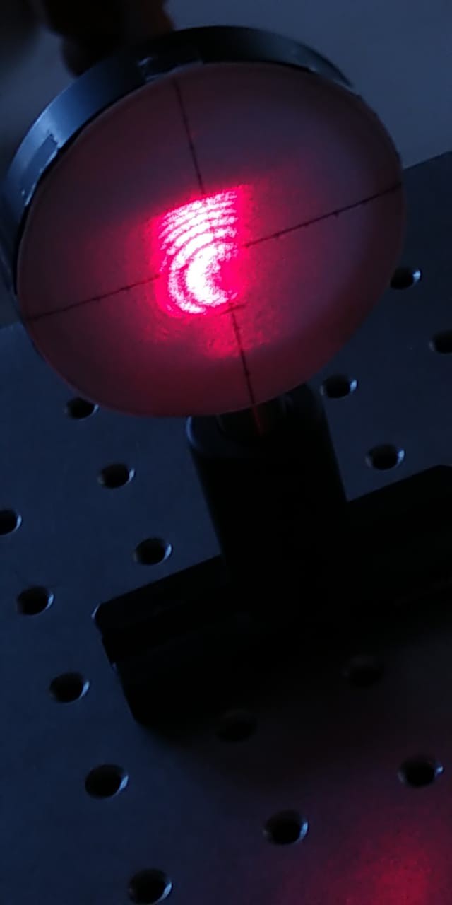
The interferogram, which is the raw interference pattern, is then captured on a screen. The appearance of circular fringes in the interferogram is a key indicator of proper alignment. These fringes arise from the interference of wavefronts with a slight difference in their angle of incidence, signifying that the mirrors are well-aligned and the optical system has a near-perfect geometry.
Next Steps
Moving forward, our next step is to design and implement a detector circuit to electronically capture the interferogram. We will also publish a detailed note explaining the importance and functionality of retroreflectors in interferometry, highlighting why they are superior to plain mirrors for applications requiring high precision.
Discussions
Become a Hackaday.io Member
Create an account to leave a comment. Already have an account? Log In.