JP Gleyzes
Features
On an RC plane, propeller performance depends on pitch, diameter, profile, and material.
Testing your propellers will allow you to measure and improve their efficiency.
This motor + propeller test equipment will measure:
- Thrust
- RPM
- Current
- Voltage
- Electrical power
- Temperature
This project is an improved version of https://hackaday.io/project/202213-rc-motor-propeller-test-bench
Compared to V1 version we can now access to :
- torque
- mecanical power
- motor efficiency
- propeller efficiency
It can be controlled either manually via a servo tester or your radio transmitter/receiver or automatically via your Android phone.
Schematics
- The heart of the system is based on a Lolin32 lite ESP32 microcontroler.
- Then a bunch of sensors are added to measure all the parameters.
- An Oled dispaly is (optionnaly) there to help debug or usage without smartphone
Bill of material can be found here : RC motor tester V2 BoM
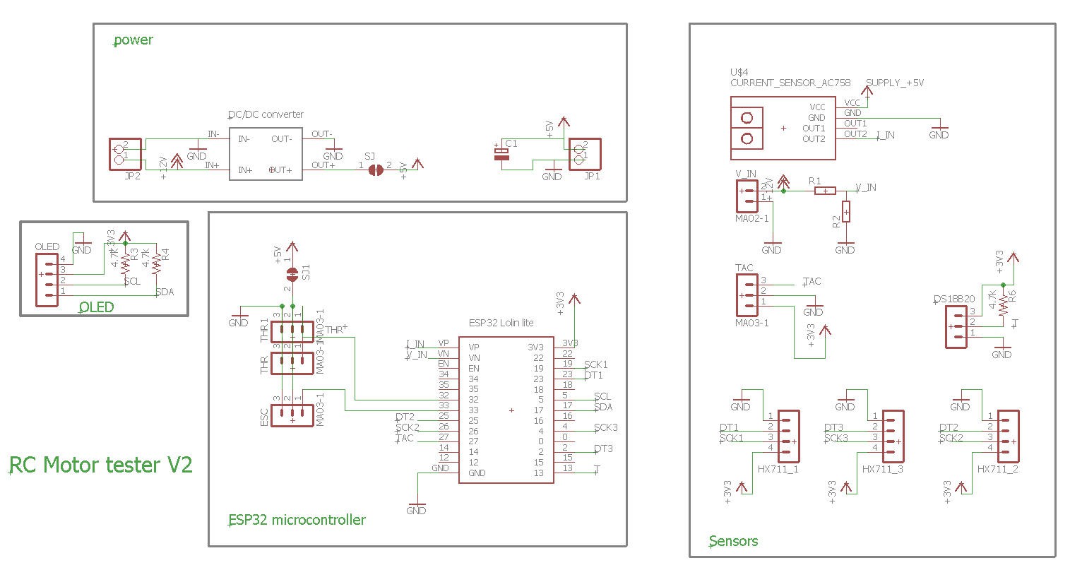
This schematics is pretty much identical to the V1, simply 2 more load cells have been added . One is for torque measurement and the other one is for spare !
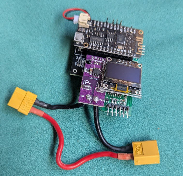
PCB
I have designed a nice and compact PCB allowing to fit the ESP32 and to connect all the sensors
The PCB was kindly sponsored by PCBWay and is as usual of excellent quality.

You can order it here: PCBWay shared project. It's cheap, delivered very fast and so professional looking!
And if you are new to PCBWay please use this affiliated link : https://pcbway.com/g/o35z4O
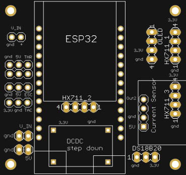
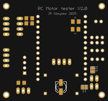
Soldering this board was easy and result is a "mezzanine board" at three floors !
Power considerations
5V can be delivered either by the DC/DC converter (prefered solution) or directly by the ESC of your plane
power with DC/DC converter :
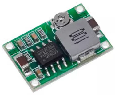
- first tune the trim pot value in order to get less than 5V (4.8V) output (do not power anything else before...)
- when this 5V is achieved, you can paint the trim pot with a drop of nail varnish to fix the potentiometer
- then (and only then) solder the SJ solder pad on the bottom side of the PCB. The 5V will now flow to the DFPlayer and the ESP32 (via the battery connector)
- Do not solder the SJ1 solder pad
using the DC/DC will insure a stable 5V supply which is used by the current sensor. Zero current is half the 5V supply. So this value ("5V") must be stable. If powered by the ESC, the "5V" could be as well 4.8V of 5.2V... this would induce a biais into the idle current measurement from ESC to ESC... So it's better to have a consistant "5V" which will allow to calibrate properly the current sensor.
Power with the ESC :
If your ESC is equiped with a strong enough BEC (1A for the ESP32) you can power the board and the ESP32 directly with the ESC connector :
- do not solder the SJ solder pad (nor the DCDC module if you want)
- solder the SJ1 solder pad
- connect the ESC servo pin header to the ESC connector on the board and power your ESC
I however do not recommand this second option (power with the ESC) as the 5V delivered by the ESC would change form ESC to ESC... see above...
Power with the USB plug :
It is safe but not reliable for exactly the same reason as above.
However you can power the device by the DC/DC converter (or the ESC) AND plug safely your USB to the PC for debugging purposes.
sensors
Six sensors are there to measure the parameters of your motor and propeller:
- ADC to measure battery voltage
- current sensor to measure current flowing into the motor
- IR sensor to measure rotation speed of the propeller
- temperature sensor to prevent over heating of the controller
- load cell sensor to measure the "weight" of the propeller (converted to thrust !)
Links for these sensors are provided into the bill of material
ADC
Voltage of the battery is directly measured by one of the ESP32 ADCs
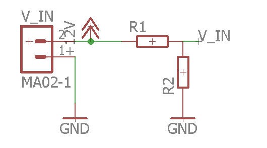
R1/R2 are a voltage divider needed to decrease the battery voltage to the ESP32 range (3V)
V_IN = R1 x Vbat / (R1 +R2)
So you have to be careful when selecting these resistors depending on the maximum voltage you plan to use for your battery.
Here are the values for a lipo 3s battery (my prefered setup!)
With R1 = 20k and R2 = 6.8k you will get max 3.3V with a fully charged lipo at 13V (3x 4.3V = 13V)
current sensor
To safely measure high current motors I have selected a powerful 100A current sensor : ACS758_100B
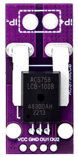
This sensor module is equiped with an operationnal amplifier on its OUT2 pin. So that you can input this pin safely on a micro controller ADC.
This sensor is "bidirectionnal" meaning that it can measure positive and negative currents. The zero value is at mid range of the ADC thus at 2.5V when the sensor is powered at 5V. This is totally withing the range of the ESP32 ADC specifications. (no need to change this OUT2 value if you measure values between 0 and 2.5V !)
LoadCell
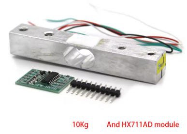
A loadcell will measure the thrust of the propeller.
I have choosen a 10kg loadcell. This device need an amplifier HX711 to adapt its value.
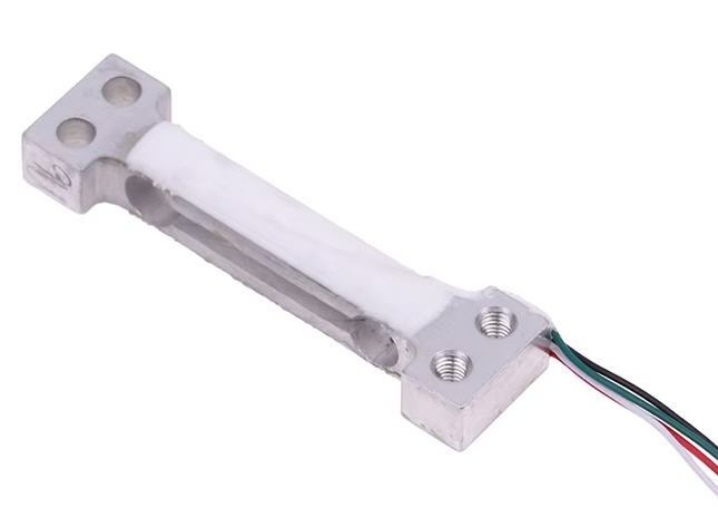
A second load cell is used to measure the torque of the motor. It will be a lighter one with only 500g capability.
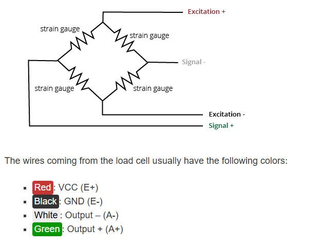
Connections between load cells and amplifiers follow this schematics:
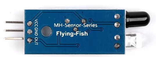
Propeller RPM
To measure the propeller speed we need to setup a tachometer. It will be made with an IR sensor. The reflection of the IR beam on the arms of the propeller will trigger interupts on the ESP32, and we will compute the rotation speed.
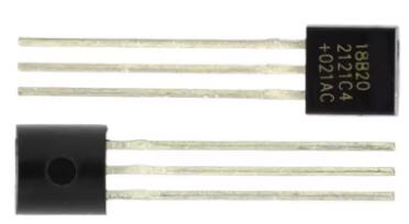
Temperature
A DS18B20 chip will take care of measuring the temperature of the ESC.
How to measure motor and propeller efficiency and torque and power
Compared to V1 version we will now access to more parameters to characterize your system. But these parameters are not "directly" measured by sensors...
Electrical power
ePow is simply the product of Voltage by Current
![]() Mechanical power
Mechanical power
In an electric motor, the mechanical power is defined as the speed times the torque.
- Speed expressed in rd/s
- torque expressed in N.m
As we measure RPM (Rotation Per Minute) we can get Speed we this simple conversion
rad/s = RPM/60 × 2π
Torque
Our second load cell will measure the strenght (F) applied by the lever attached to the body of the motor. When the propeller rotates the torque is applied on the motor body but in the opposite direction. The lever has a L = 0.0605 m length.
If F is expressed into Newton then
![]() Motor efficiency
Motor efficiency
motor effcieincy is the ratio of mechanical power by electrical power
![]() propeller efficiency
propeller efficiency
Finally the mechanical power output by the motor is directly transmited to the propeller (direct attachement of the propeller on the motor shaft)
And the propeller produces thrust which is measured by the first loadCell
Propeller effciciency is said to be the ratio between Thrust and mechanical power
However this definition found into tytorobotics blog, is not valid... An efficiency should be "dimensionless"...
A real estimate of propeller efficiency would need to have a wind tunnel to measure air speed "v".
propEff = (Thrust x v)/mPow
All these formula are handled into the android appilcation when exporting the sensors values. (See below)
Torque mechanical housing
We know now how to measure motor and propeller parameters but how to physically measure the torque ?
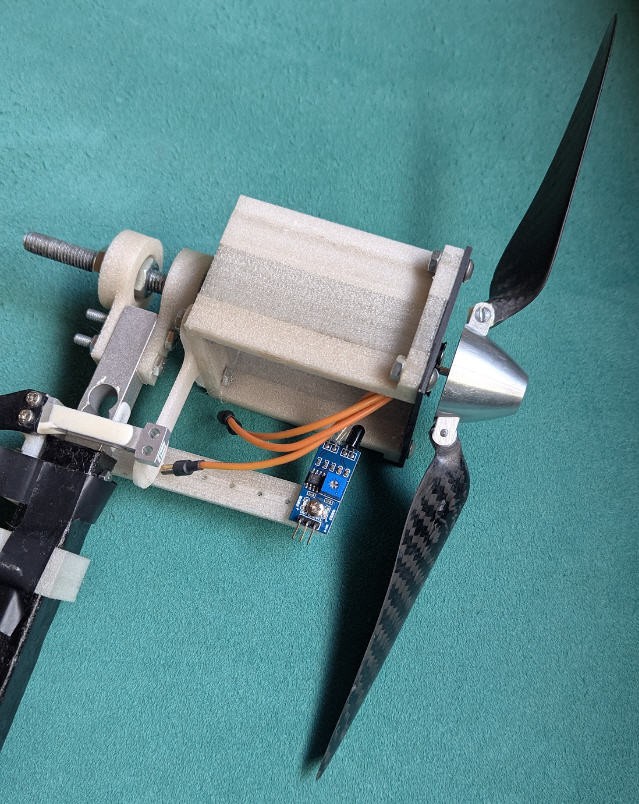
One way to do this, while allowing the motor shaft to spin, is to mount the entire motor housing on good bearings concentric with the shaft axis so it would freely spin backwards if there were any torque on the shaft. Then you can use the same arm and scale setup to measure the torque required to keep the motor housing from rotating.
This is exactly what I did when attaching the motor housing on a rotating axis while its motion will be blocked by the lever "pushing" on the torque load cell.
A picture is better than a lot of words...
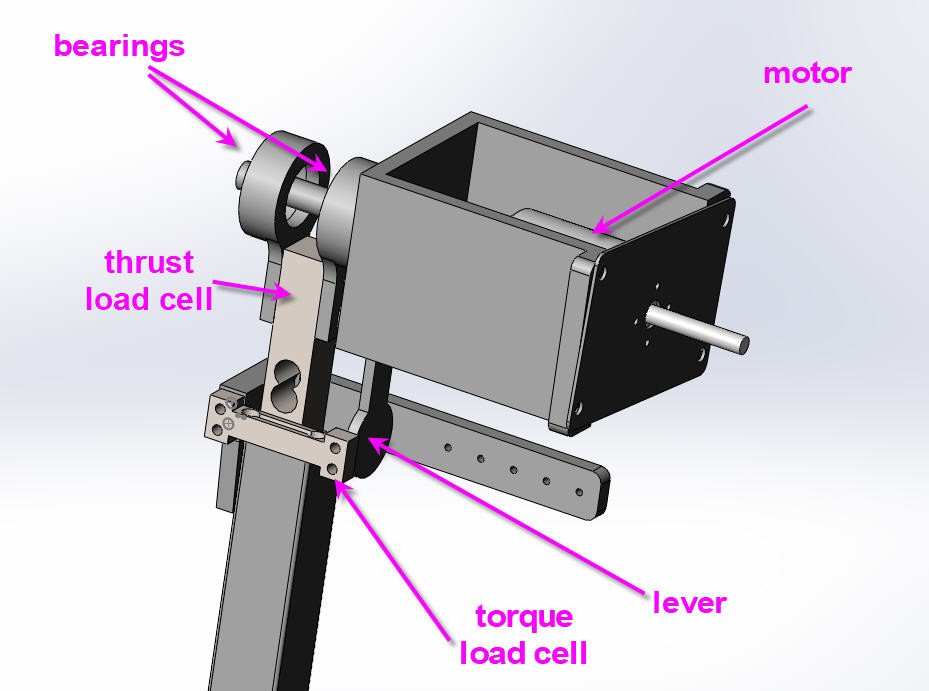
This CAD model has been 3D printed and all the stl files are accessible on thingiverse