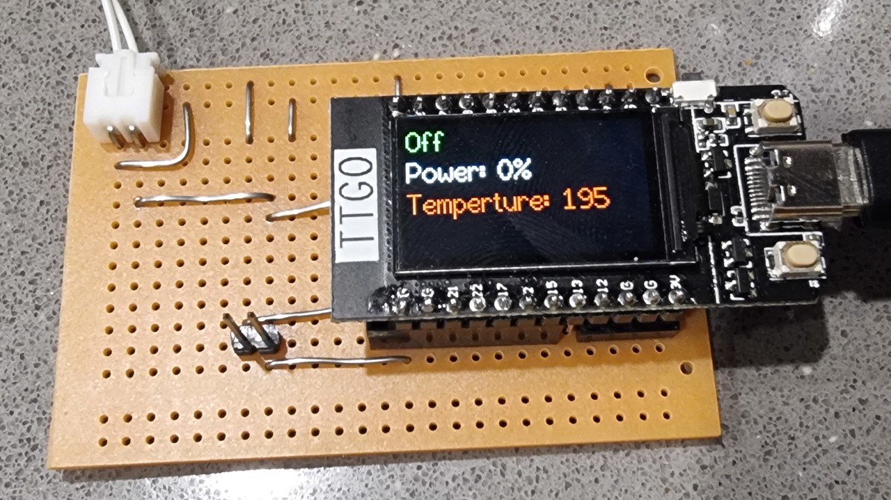
0%
0%
Another Mini Reflow Oven
Building a reflow oven from KMarts Mini Oven $35AU Appliance
 Paul J R
Become a Hackaday.io member
Already have an account? Log in.
Just one more thing
To make the experience fit your profile, pick a username and tell us what interests you.
Pick an awesome username
hackaday.io/
Your profile's URL: hackaday.io/username. Max 25 alphanumeric characters.
Pick a few interests
Projects that share your interests
People that share your interests


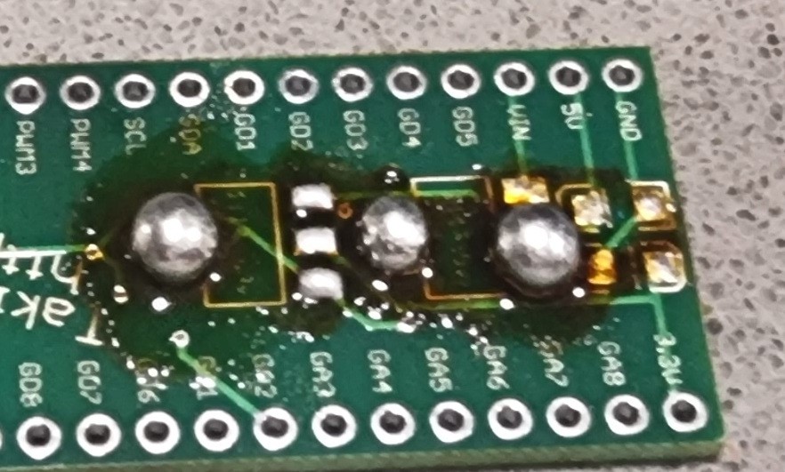
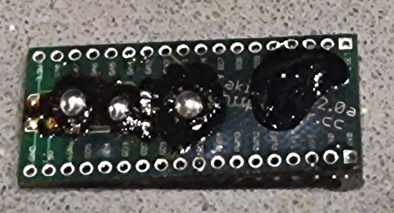

I know this is older, but I have a dash mini toaster oven (same thing) and would love to try it out! Would you mind uploading a few pictures showing where you put the board? Maybe I can finally keep from burning those chicken nuggies 😂