Sergey
*** The description is constantly updated; please ask your questions in the chat ***
Rimer SBC is based on Microchip's ATSAMD51J20A microcontroller and utilizes most of the peripherals available in the TQFP64 package: high-speed SPI for the LCD, SD/MMC card, I2C-based keyboard scanning, and EEPROM for configuration. Analog I/O is buffered and routed to a 3.5mm audio jack.
Source code and info:
You can find the latest source code and related info here.
More info, including schematics here.
Firmware + apps
** It is still in continuous development, so I'm open to suggestions **
- ucosR - an operating system based on FreeRTOS. It provides control of the program blocks called interfaces. The CLI has command history (no search yet), looping and piping ability, simple script support and a basic text editor. ucosR repository
- Basic-D - a Basic language interpreter with a complete line editor and syntax colouring.
- ZX Spectrum 48K emulator, with a debugger, .z80, and .sna snapshots support.
Implemented Interfaces:
- sys : system hardware control (reboot, off ...)
- utl : command line utility (hex, delay ...)
- set: system settings (colours, volume, font ...)
- aio: analog IO ports control (dac, adc ...)
- dio: digital IO port control (pwr, dir, pin ...)
- sio: serial IO ports control (mode, tx, rx ...)
- eep: EEPROM utilities.
- sd: SD FAT control (ls, rm ...)
- bas: Basic-D interpreter.
- mem: RAM utilities.
- zx: ZX Spectrum 48K emulator.
uCU
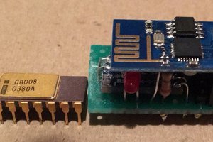
ATSAMD51J20A running at 120 MHz. It has 1 MB of flash and 256 kB of RAM.
LCD
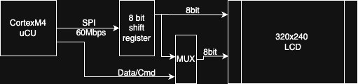
3.2 inch 240x320 IPS TFT LCD with ST7789 controller. It's controlled by SPI, later deserialized and fed to the parallel port, reaching up to 60 fps. The firmware uses a frame buffer, which is transferred to the LCD by DMA.
KEYBOARD
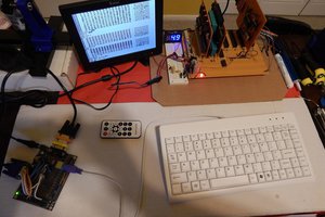
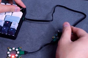
A 40-switch mechanical keyboard (Kailh low-profile Choco) was originally designed to be compatible with the ZX Spectrum layout. The default stickers have more common secondary character sets but can be easily customized. The keyboard is scanned by an I2C GPIO expander and connected to the microcontroller by the I2C bus:

GPIO
An ESD protected GPIOs are routed to three 2.54mm connectors (4+8+8 pins)
| Rimer SBC port | ATSAMD51J20A GPIO | SERCOM | TC | TCC |
| Port0, J6.1 | PB02 | SERCOM5.PAD0 | - | - |
| Port0, J6.2 | PB03 | SERCOM5.PAD1 | - | - |
| Port1, J7.2 | PA16 | SERCOM1.PAD0 | - | - |
| Port1, J7.3 | PA17 | SERCOM1.PAD1 | - | - |
| Port1, J7.4 | PA18 | SERCOM1.PAD2 | - | - |
| Port1, J7.5 | PA19 | SERCOM1.PAD3 | - | - |
| Port1, J7.6 | PA20 | - | - | TCC0.WO0 |
| Port1, J7.7 | PA21 | - | - | TCC0.WO1 |
| Port2, J8.2 | PA12 | SERCOM2.PAD0 | - | - |
| Port2, J8.3 | PA13 | SERCOM2.PAD1 | - | - |
| Port2, J8.4 | PA14 | SERCOM2.PAD2 | - | - |
| Port2, J8.5 | PA15 | SERCOM2.PAD3 | - | - |
| Port2, J8.6 | PA00 | - | TC2.WO0 | - |
| Port2, J8.7 | PA01 | - | TC2.WO1 | - |
Three I/O connectors are wired to the SERCOM ports: one is limited to two serial lines (I2C and UART), and two others have full 4-pin ports. Two TC and two TCC channels are routed to GPIO connectors.
All GPIO ports have separate power controls with the current limits: Ports 1 - 125mA, Ports 2 and 3 - 300mA.
... to be continued ...
 hogan96
 Stephan Bourgeois