 Schwimmflugel
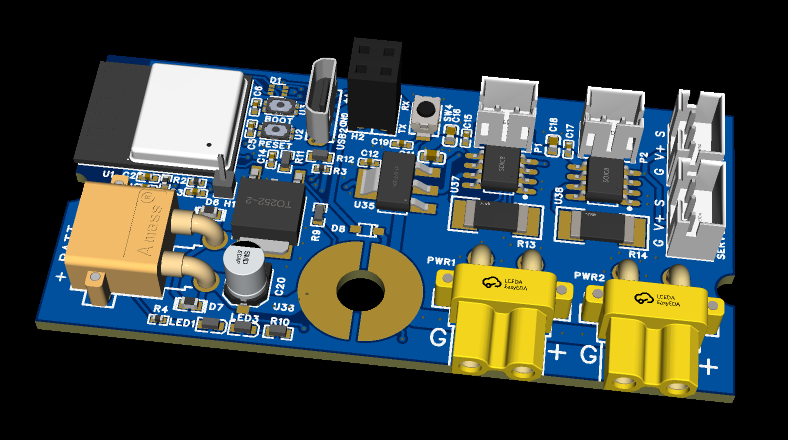
Board Design Overview
EDA Tool: EasyEDA
Manufacturer and Assembly: JLCPCB
Microcontroller: ESP32-C3-Mini
Features:
- 1 high current LiPo input
- 1 master safety switch
- 2 high current outputs for ESC's or others
- 2 Servo/ESC/PWM outputs
- 2 DRV8870 Brushed Motor H-Bridge Outputs
- 1 Debug LED
- 1 user programable button
- Native USB connection
- UART (TX/RX) optional connection (can be repurposed for additional I/O)
- 1 additional /O port that can be soldered to
- WIFI and BLE support with the ESP32-C3-Mini preassembled PCB antenna
Lessons from Version 1: Refining My Combat Robot Control Board
Version 1 of this design was my first attempt at creating a versatile combat robot control board—one that could be easily integrated into different robots without requiring custom PCBs for each build. However, as I started designing my first robot around it, I encountered several challenges that needed to be addressed.
Connector Placement Issues
The XT30 connectors for the LiPo battery made board installation more difficult than expected. The additional space required for both the connectors and their wire leads took up valuable real estate on the PCB. I realized that using solderable pads instead of through-hole connectors would allow wires to be soldered at a more convenient angle, simplifying routing and making push connections easier to manage.

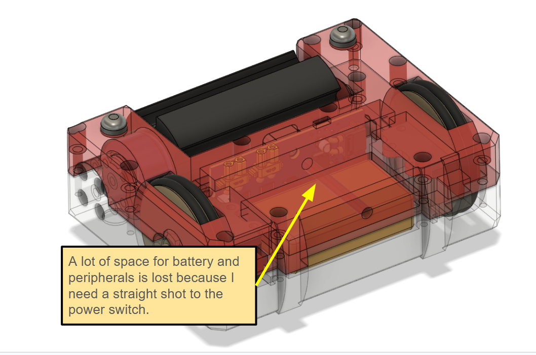
Master Power Switch Accessibility
The placement of the master power switch also posed an issue. It needed to be easily accessible with a tool, without requiring the robot to be disassembled. This meant ensuring that no batteries or other components were mounted above or below the board, as a screwdriver needed a clear path to torque down the switch. This wasted a lot of potentially usable volume to house other peripherals.
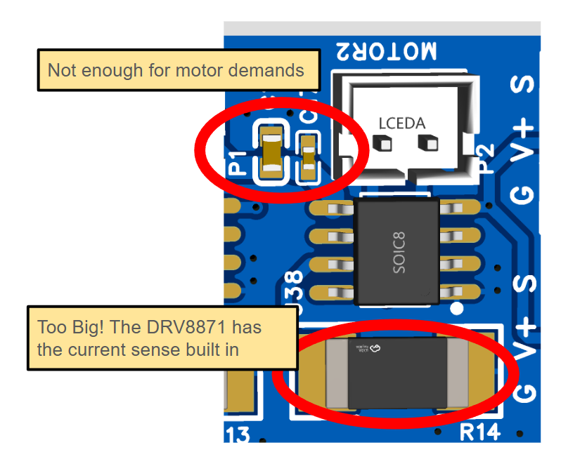
Motor Driver & Thermal Issues
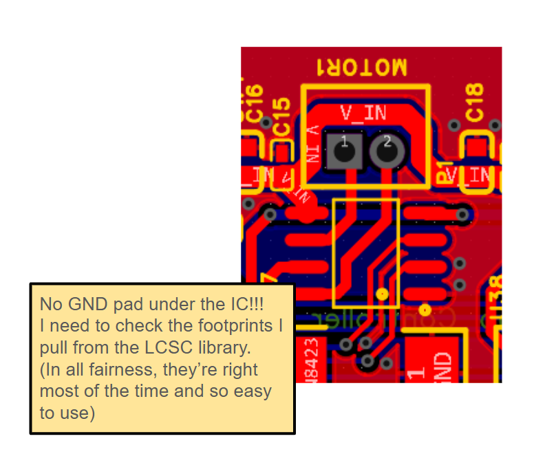
The DRV8870 motor drivers were non-functional, and I discovered that the GND plane beneath the IC was not exposed—an important reminder to always double-check footprint details from EasyEDA/LCSC! Without proper thermal dissipation, the ICs likely entered rapid thermal shutdown during testing. Additionally, the current sense resistor was oversized, while the power input capacitors for the DRV8870 were undersized.
To address these issues and improve performance, I decided to switch to the DRV8871 in the next revision, as it offers better built-in features and should handle heat dissipation more effectively when I actually include proper grounding.
Improving Debugging & Status Indicators
The single debug LED provided minimal visual feedback for board status. To make fault detection and battery level monitoring more intuitive, I plan to replace it with an WS2812 RGB LED, allowing for clearer visual indicators.
Discussions
Become a Hackaday.io Member
Create an account to leave a comment. Already have an account? Log In.