 Schwimmflugel
After spending some time testing the new revision of my combat robot control board and refining the firmware, it's finally performing as expected. In this post, I’ll go into more detail about the board’s functionality and features.
I’ve included a quick overview video, but if you're looking for the full breakdown, keep reading!
Features Overview
This second revision of the combat robot control board was built with modularity, compactness, and power in mind—making it easy to integrate into a variety of designs while supporting high-current loads and reliable wireless control. Here's a breakdown of the main features:
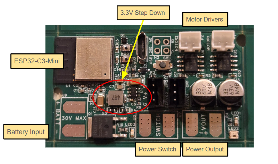
ESP32-C3-MINI
At the heart of the board is the ESP32-C3-MINI with a built-in PCB antenna for Bluetooth Low Energy communication with an Xbox controller. It offers plenty of GPIO for controlling onboard components, with additional pins available for UART and future expansions.
High-Current DC Input
Designed to accept up to 30V DC, the board features reverse polarity protection and large, easily solderable input pads. The power input is protected for continuous draws up to 30A—though trace limits are still being tested. With a 4-layer PCB and wide copper areas, it should hold up under combat conditions.
3.3V Step-Down Converter
A robust AP63203 buck converter supplies a regulated 3.3V output at up to 2A. This powers the ESP32-C3 and also provides clean power to external peripherals and sensors.
Dual DRV8871 Motor Drivers
Two onboard DRV8871 drivers deliver up to 2A each to brushed DC motors—ideal for robot drive systems. They’re compact, thermally improved over the previous version, and simple to control via PWM.
External Switch Connector
For safety and convenience, a pair of solder pads allows you to add a remote-mounted power switch—acting as a master cutoff without obstructing access to the board.
High-Current Output Pads
Parallel to the main power input, these pads allow direct connection to ESCs or other high-current devices, simplifying power distribution within the robot.
User I/O and Debug Tools
The board includes a basic debug LED, a tactile pushbutton for custom input, and two I/O headers with 3.3V and GND pins for expansion or prototyping.
Discussions
Become a Hackaday.io Member
Create an account to leave a comment. Already have an account? Log In.