 ziggurat29
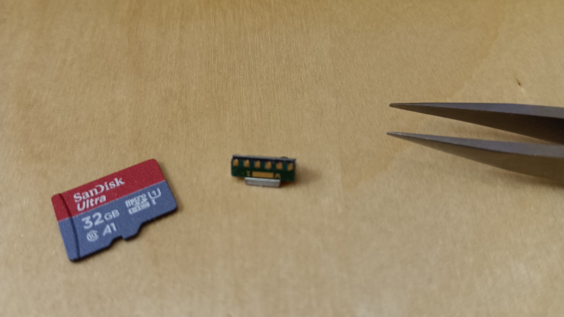
Today I set out on the fiddly affair of making a wired connection between the BluePill and the IrDA transceiver. The transceiver requires a couple passives: a series dropping resistor for the IR LED (so you can tune for power budget), and a couple bypass caps (to provide some impulse capability when driving the LED).
This is somewhat fraught because the modules are SMD, and typically at a fine pitch of 50 mil. I am using some obsolete NOS parts from surplus which cost me USD $2 ea. So I got 10. Because I know I'm going to break some, and because I know I'm going to want some more. (And you really want two, because otherwise who are you going to talk to?)
Anwyay, I chose to do the 'circuit sculpture' technique of wiring in free space with no PCB, just without the aesthetic. This is a slow process, so I don't recommend it in general, but if you just want a couple and have the time and patience to spare, it can be done.
I wound up making one for breadboard, and one for wiring permanently.
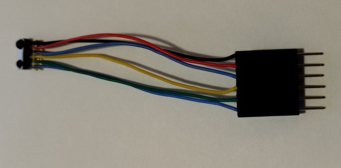
The breadboard adapter is pretty easy to fabricate:
- put some flux on the part
- make solder balls on the pads
- cut 24 AWG wires
- put flux on ends of wires
- touch the soldering iron to the wire and the solder ball pad and it's done
- crimp the other ends to terminator of choice
- create strain relief near the transceiver module by squiring some substance-of-choice (I used UV cure resin, "Bondic"; hot glue is probably an option) Adding the strain relief is recommended to avoid breakage at the solder pads of the device. If that happens then the party's over.
The breadboard is easy because the passives can be on the breadboard. But this confines you to a breadboard.
The free-space-wired dedicated module is a little more tricky since you're doing 'circuit sculpture', but it can be done.
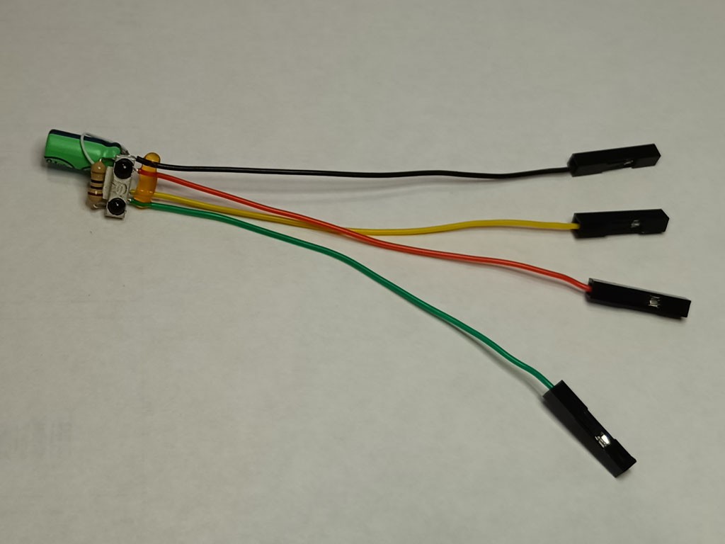
I crimped terminators on mine simply because my BluePill already had pin headers soldered on.
Final connection is trivial:
- power (3.3 V) and ground
- PB11 -- detector, (here shown Yellow)
- PB10 -- emitter, (here shown Green)
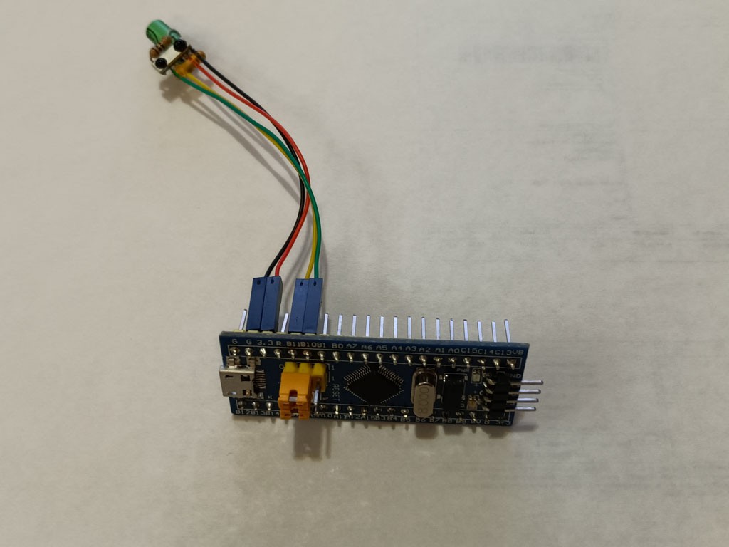
You'll possibly want two! I had my breadboard unit in addition to this one, so I was able to open two terminals and see data exchanged in both directions between the two.
Discussions
Become a Hackaday.io Member
Create an account to leave a comment. Already have an account? Log In.