 Collin Matthews
As alluded to in the last post, making a wide band transformer coupled amplifier is challenging. More challenging then I initially thought. Below are some notes as I worked towards an optimized transformer.
Initial Design
Starting out, I knew I needed to minimize leakage inductance and inter-winding + cross winding capacitance. This is the key to any high performance transformer, especially at high frequencies.
When talking about parasitics, there are two main ideas. Both are at odds with each other:
- To minimize leakage inductance, typically you want a single layer of wire, wound on top of another single layer. This comes at the price of increased capacitance, and risk of electrical breakdown.
- To minimize parasitic capacitance, you want minimal windings, and maximum distance between windings and turns. This increases leakage inductance.
Transformer design typically comes down to finding a compromise and that is hard to do without complex simulations or just building up some designs and taking tests. So I used my experience in building SMPS transformers to guesstimate a starting point.
U-Core Design

Starting off, since this was going to be a high voltage and high frequency design, I have never used u-core ferrite, but it is what is used in old high voltage TV flyback transformers. I figured leakage inductance would be an issue, but the separation of windings would make parasitic capacitance nearly non-existent.
In the image above, you can see two windings on the transformer and two more I made to take measurements with. just different winding counts and 28-40AWG to fit as many turns on a single layer as I could.
I shot a video of winding these transformers, basically just a Kapton film that has wire wound on top of it. I tried optimizing winding counts to see if there was any room for improvement, but the U-Core just had to low of permeability, requiring a lot of windings to get the needed inductance and thus incurring leakage inductance and capacitance. In the end what I was after was not that. So both the shape and actual material were less then ideal.
German Ferrite To The Rescue
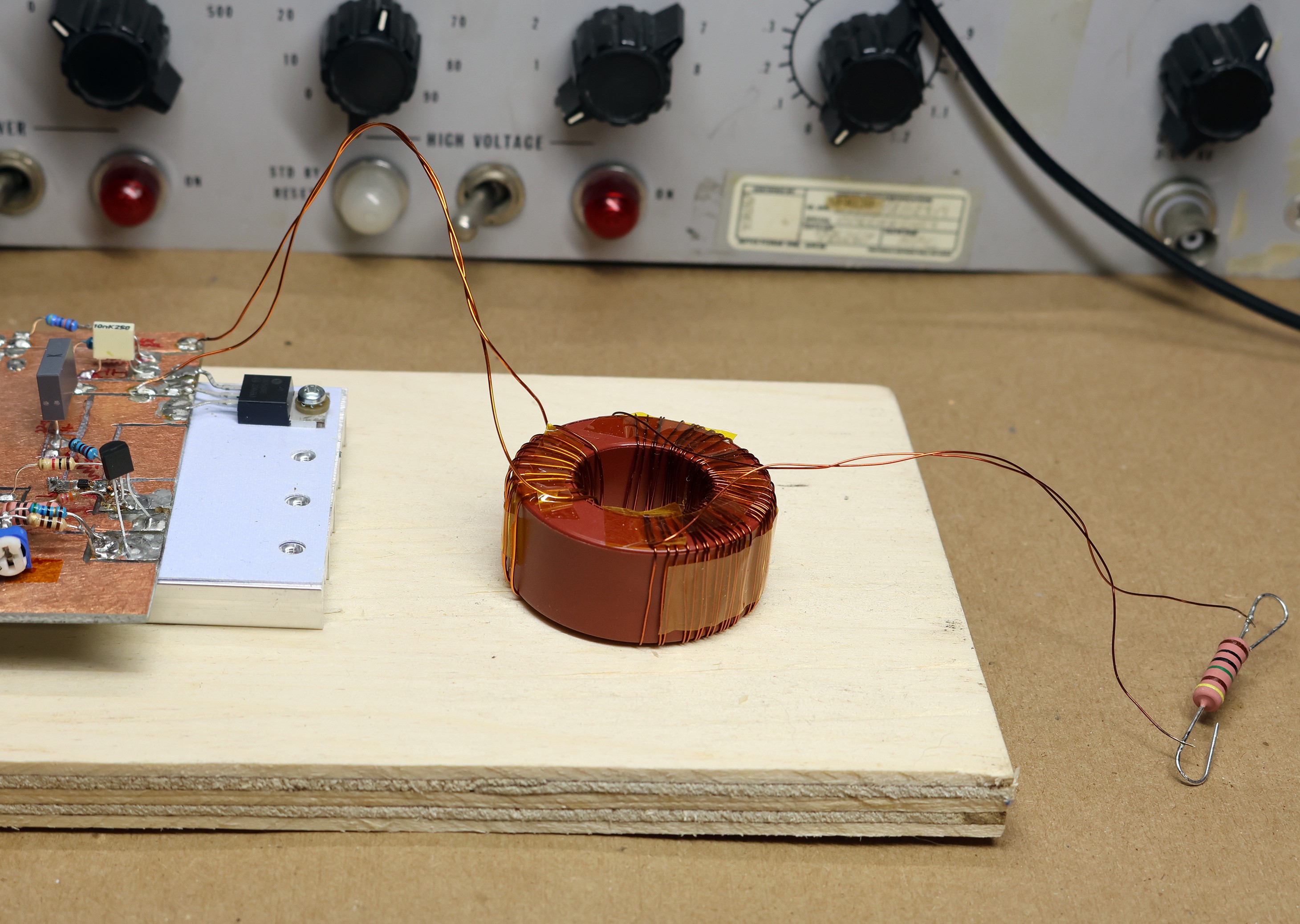
After some googling, I found a German company (Vacuumschmelze) making torrids with a nano-crystalline high performance material, This would give me 10x more permeability, and basically allow me to reduce my windings by 5-10x for the same inductance values, resulting in lower parasitics. This material also has a higher saturation point vs typical ferrite (1.2T vs 0.4T)
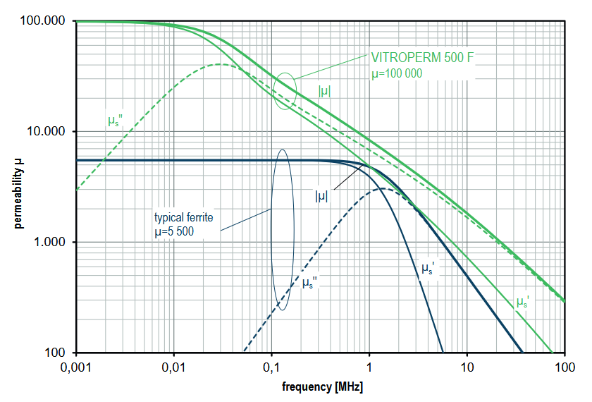
Looking at the picture below, the green is the new material / transformer. The blue is a typical ferrite. My u-cores actually had a permeability of ~2000, so even worse then this plot shows. If you are not a transformer expert higher permeability means:
- Less turns for same inductance, thus less parasitic.
- The magnetic flux is less likely to leak out of the core, thus less parasitics.
The cores are more expensive then typical, but if you work with magnetics ever, I strongly recommend you check this stuff out.
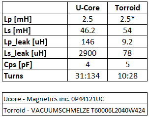
Below is a chart of real measurements of the transformers shown above. Note the Torrid has 10uH primary inductance at lower frequencies hence the '*'. You should note the massively better leakage inductance results.
Discussions
Become a Hackaday.io Member
Create an account to leave a comment. Already have an account? Log In.