 Collin Matthews
Changes made to improve performance:
- Using the new transformer that has significantly better parasitic/leakage characteristics.
- Replacing the JFETs with Depletion FETs (DN2540).
- New 180V power supply to allow higher then 30mA bias current.
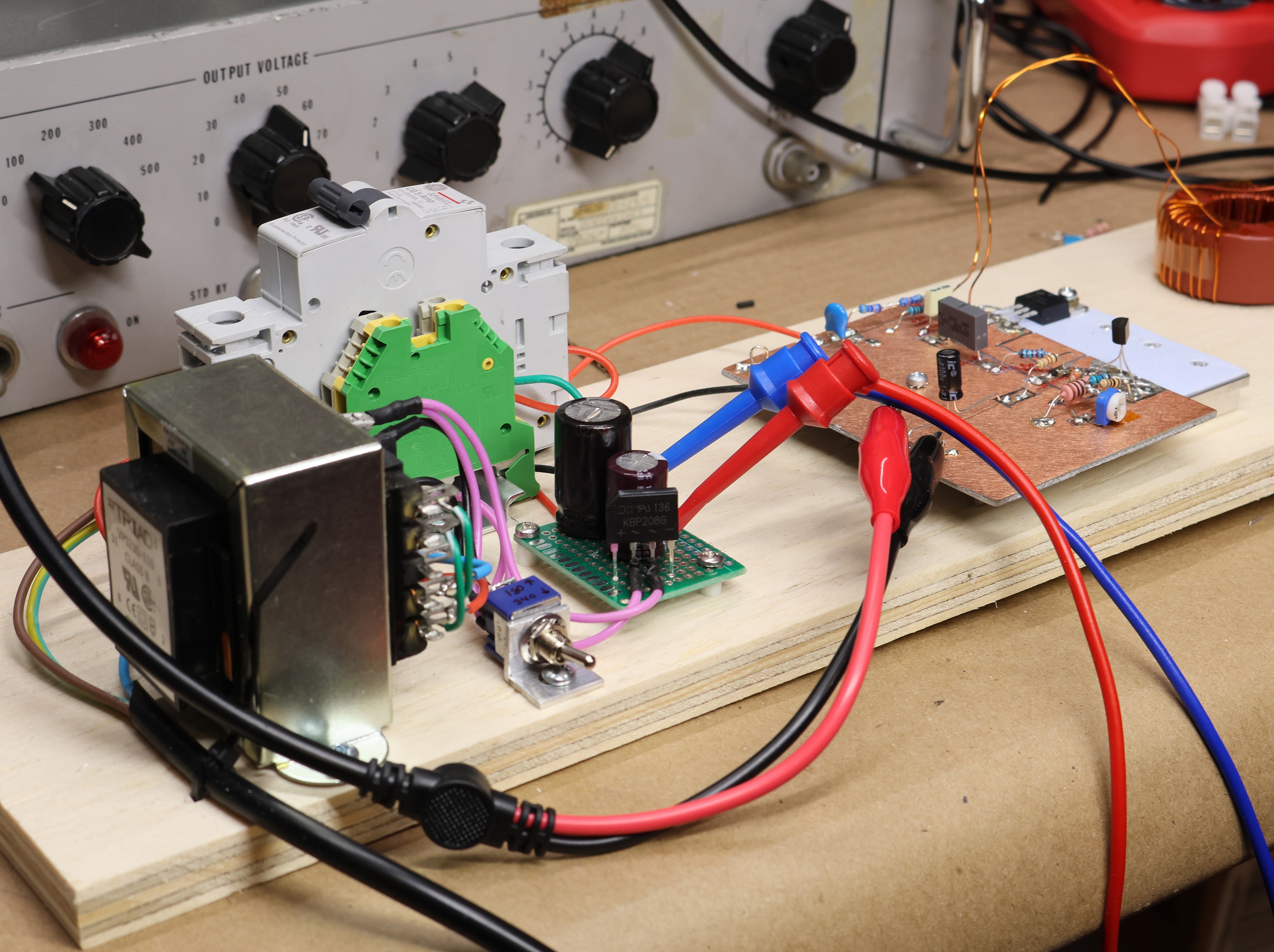
The new power supply was just an isolation transformer (120/240 windings), with a bridge rectifier, and a switch to flip the output between series and parallel for a 120 or 240 AC output (180 or 340 DC). The image below has the new setup.
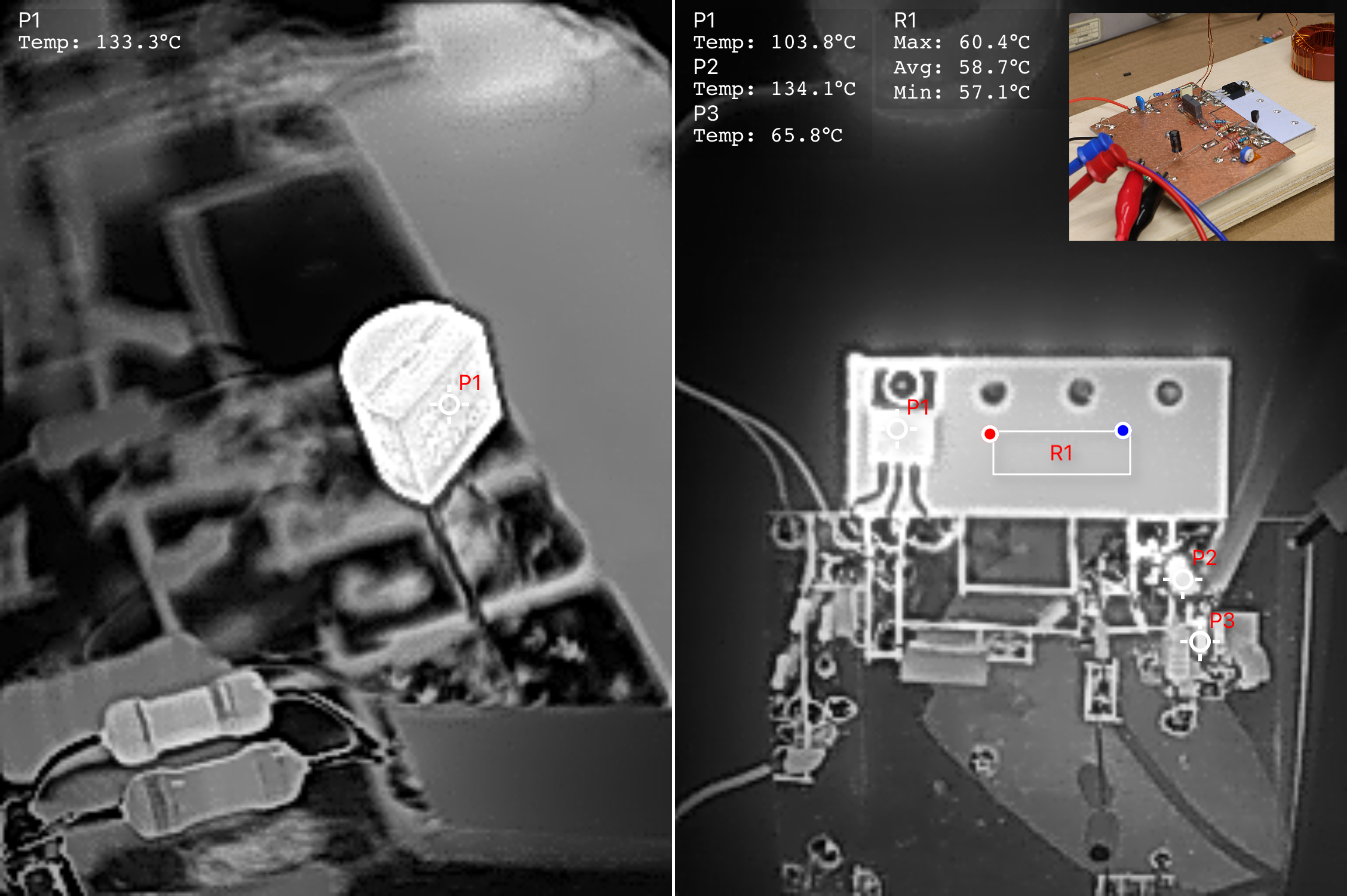
After all the changes the amplifier showed significantly better performance. With the new power supply I am able to push at-least 100mA of current as opposed to my limited Fluke supply of 30mA. The next challenge is a thermal one, so I used a thermal camera to examine the actual operating temperatures. I was concerned about the 2 transistors mainly, and at ~65mA of Bias the lower cascade TO-92 was slightly beyond its 1W rated operating point, with a temperature of 133C.
Here is a newer shot of the 3dB performance.
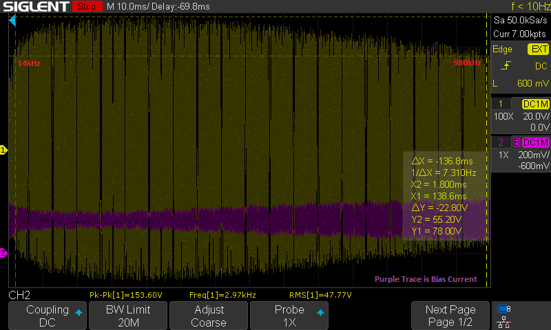
Unfortunately I found after taking this picture the circuit is highly sensitive to capacitance loading on the output. This was using a 100:1 scope probe with a 7pF capacitance. Putting a 10:1 probe with 17pF greatly reduced the 3dB bandwidth to ~650kHz from the ~1Mhz shown in this image.
So it continues to appear that a transformer coupled high voltage amplifier is probably not a great design. If I used huge amounts of bias current, the feedback could compensate but the power dissipation would be an issue long before achieving significantly better performance.
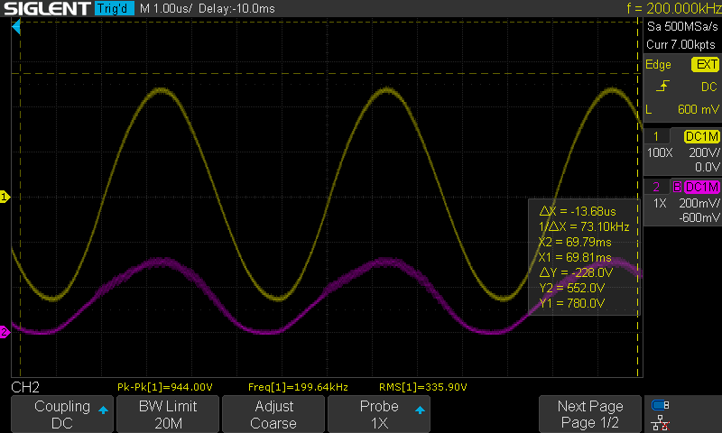
At a more reasonable frequency like 200kHz, this amplifier does perform well with minimal output capacitance. For example, we achieve 1kVpp below at 200kHz, this is 600V/uS slew rate which is a decent accomplishment, and on-par with real lab solutions although the drive capability of this amplifier needs fairly ideal conditions.
Also note you can see the malformed bias current waveform, this is due to bottoming out the current to 0mA every cycle, the only reason the output wave is not distorted is due to the inductor supplying that current for a short period. Basically this is the maximum gain without more bias current.
Discussions
Become a Hackaday.io Member
Create an account to leave a comment. Already have an account? Log In.