 Silícios Lab
Introduction
The purpose of this project is to develop a printed circuit board (PCB) that allows weight measurement using a load cell and the HX711 converter. The electronic design community will be able to use this PCB for learning, experimenting, and implementing load measurement systems.
Click in this link to download the PCB Gerber file.

Load cells work based on mechanical deformation that generates a variation in electrical resistance, converted into an electrical signal proportional to the weight applied. The HX711 is a high-precision analog-to-digital converter (ADC) designed to amplify and digitize these weak signals, allowing direct interfacing with microcontrollers. In this project, we will use the ESP32 to read the HX711 and process the data obtained.

This project can be applied in several areas, including electronic scales, load monitoring in structures, and IoT systems for remote weighing.
Click in this link to download the PCB Gerber file.
Printed Board Specifications
The PCB was designed to be compact and optimized for accurate weight measurements. Below are the main specifications and features of the board:
Dimensions and Layout: The PCB has a compact design, allowing easy integration into different applications. The tracks were strategically positioned to minimize interference and optimize communication between components.
Main Components:
- Load cell: Responsible for converting the applied force into an electrical signal proportional to the weight.
- HX711: 24-bit analog-to-digital converter that amplifies and digitizes the signal from the load cell.
- Power and communication connectors: Allow interfacing with the ESP32 and proper powering of the circuit.
- ESP32 as a microcontroller: Responsible for processing the data acquired by the HX711 and communication with other devices.
- 100nF decoupling capacitor: Helps stabilize the HX711 power supply, reducing noise and improving reading accuracy.
Power supply: The board can be powered by 3.3V or 5V, making it compatible with different microcontrollers and applications.
Interfaces and Connectors:
- Load cell connector (4 wires): Allows direct connection of the load cell to the circuit.
- Digital communication pins (HX711 -> ESP32): Responsible for transmitting the measured data.
- Power supply and expansion terminals: Allow the addition of external modules, such as displays or wireless communication.
This project was developed with the aim of providing an affordable and reliable solution for weight measurements. Below, images of the PCB will be presented for a better understanding of the circuit design and layout.
Click in this link to download the PCB Gerber file.
Sensor and IC HX711 Operation
To understand how the HX711 and the load cell work, it is essential to know the operating principle of these components. The load cell converts the applied force into a variation in electrical resistance, which in turn generates a small voltage difference. However, this signal is extremely weak and requires amplification to be processed properly.
The HX711 plays this role by amplifying and converting the analog signal into digital, enabling it to be interpreted by a microcontroller such as the ESP32. In addition, the HX711 has a simplified two-wire interface for communication with microcontrollers, making its integration easy and efficient.
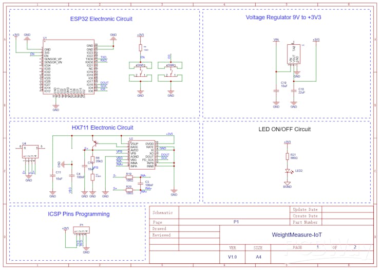
Below was presented all electronic schematic of the electronic circuit.
Next, we will explain in more detail the operating principle of the load cell.
Click in this link to download the PCB Gerber file.
Load Cell Operating Principle
The load cell is a transducer that converts mechanical force into electrical resistance variation.
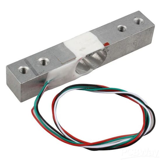
This variation is measured by a Wheatstone bridge, generating a small voltage signal proportional to the applied weight.
HX711 Amplification and Conversion
The HX711 is a 24-bit ADC designed to measure weak signals from load sensors. It amplifies the load cell signal and converts it to a digital format, allowing communication with microcontrollers through a two-wire interface (Clock and Data).
Decoupling Capacitor
To improve the stability of the HX711 power supply and reduce interference, a 100nF capacitor was added between the VCC and GND pins of the circuit. This capacitor helps filter high-frequency noise, ensuring more stable measurements and reducing variations caused by fluctuations in the supply voltage.
Pinout Configuration
- VCC: Power supply (3.3V or 5V)
- GND: Ground
- DT (Data): Data output
- SCK (Clock): Clock pulse for reading data
- E+ / E- / A+ / A-: Connections for load cell
Schematic and PCB Layout
The PCB was designed to ensure efficient and reliable operation of the weight measurement system. The design includes a strategic arrangement of components to minimize noise and electrical interference, as well as an optimized distribution of the tracks to ensure efficient communication between the modules. In addition, decoupling capacitors were used to ensure power supply stability and measurement accuracy. The main elements present in the circuit are detailed below.
The circuit includes:
- HX711 connected to the load cell via the Wheatstone bridge.
- Noise filters (capacitors) to ensure more stable measurements.
- Connectors for ESP32 that allow easy integration with other systems.
- Optimized tracks to minimize interference and electrical noise.
- 100nF capacitor next to the HX711, ensuring power supply stability.
- The PCB was designed to be easy to assemble and compatible with different load sensor configurations.
Next, we will understand how to carry out the process of calibrating and measuring the weight of objects.
Programming for Calibration and Weight Measurement
Programming involves three main steps: reading the HX711, calibrating the load cell, and converting the signal into usable values.
Code to get the calibration factor
This code allows you to calibrate the load cell by setting a calibration factor based on a known weight.
#include <HX711.h> #define DT 16 // Pino de Data (DT) do HX711 #define SCK 4 // Pino de Clock (SCK) do HX711 HX711 balanca; // Peso conhecido para calibração (85g) float pesoConhecido = 85.0; // Peso de 85g void setup() { Serial.begin(115200); // Inicializa HX711 nos pinos DT e SCK balanca.begin(DT, SCK); // Aguarda estabilizar Serial.println("Iniciando..."); delay(2000); // Faz a tara (zera a balança sem peso) Serial.println("Tara em andamento..."); balanca.tare(); Serial.println("Tara concluída."); Serial.println("Coloque um peso de 85g na balança."); } void loop() { // Verifica se o HX711 está pronto para leitura if (balanca.is_ready()) { long totalLeituras = 0; int numLeituras = 50; // Número de leituras para calcular a média // Realiza múltiplas leituras e soma os valores for (int i = 0; i < numLeituras; i++) { totalLeituras += balanca.get_value(10); // Média de 10 leituras delay(50); // Pequeno delay entre as leituras } // Calcula a média das leituras long mediaLeitura = totalLeituras / numLeituras; // Calcula o fator de calibração float fatorDeCalibracao = mediaLeitura / pesoConhecido; // Exibe a média da leitura e o fator de calibração Serial.print("Média da leitura bruta: "); Serial.println(mediaLeitura); Serial.print("Fator de Calibração: "); Serial.println(fatorDeCalibracao); // Aguarda 5 segundos antes de fazer nova calibração delay(5000); } else { Serial.println("HX711 não está pronto."); delay(500); } }
Next, we will explain the code to get the calibration factor.
The HX711.h library is included in the code to enable communication with the HX711 module, which is responsible for amplifying and converting the analog signal from the load cell to digital values.
#include <HX711.h>
Here, the ESP32 pins are defined to connect to the HX711:
DT (Data) → Pin 16
SCK (Clock) → Pin 4
#define DT 16 // Pino de Data (DT) do HX711 #define SCK 4 // Pino de Clock (SCK) do HX711
Creating the HX711 Object
Now, will be create the HX711 object.
HX711 balanca;
An instance of the HX711 class scale object is created, which will be used to interact with the HX711 module.
Definition of Known Weight
float pesoConhecido = 85.0;
Since the calibration process requires a reference weight, here we define 85g as the reference weight. Feel free to use another value. Remember to change the 85g value in the programming to the weight you will use as a reference.
Now, will see the setup function.
Initial Configuration (setup)
Initializes serial communication with the serial monitor at 115200 baud rate, allowing information to be displayed on the computer.
void setup() { Serial.begin(115200);
After that, it is necessary to initialize the scale by configuring the DT and SCK pins of the HX711.
balanca.begin(DT, SCK);
Now, will see the tare process.
Tare process
Tare means zeroing the scale, i.e. removing any residual weight before calibration. The tare() method adjusts the reading to zero before weighing.
Serial.println("Tare in progress..."); balanca.tare(); Serial.println("Tare completed.");
Displays the message "Tare complete."
Prompts User to Enter Known Weight
The system asks the user to place 85g on the scale.
Serial.println("Place a weight of 85g on the scale.");
Now, we'll discuss the void loop function.
Loop Function
First, we must check if the HX711 is ready to be read.
if (balanca.is_ready())
The code checks if the HX711 is ready to take readings. If not, it displays "HX711 is not ready."
After that, the system reads 50 values from the load cell.
long totalLeituras = 0; int numLeituras = 50; // Número de leituras para calcular a média // Realiza múltiplas leituras e soma os valores for (int i = 0; i < numLeituras; i++) { totalLeituras += balanca.get_value(10); // Média de 10 leituras delay(50); // Pequeno delay entre as leituras }
Here, 50 readings are taken from the load cell. Each reading uses get_value(10), which averages 10 samples before returning a value.
totalReadings accumulates all readings to later calculate the average.
long mediaLeitura = totalLeituras / numLeituras;
The average of the raw readings is calculated by adding the read values and dividing by the number of readings (50). With this value, we can calculate the calibration factor.
Calibration Factor Calculation
The calibration factor is a numerical value used to convert the raw readings of the HX711 sensor into actual weight values. It represents the relationship between the electrical signal generated by the load cell and the known mass used in the calibration process.
During calibration, a reference weight is placed on the scale and the system records the corresponding raw value. The calibration factor is then calculated by dividing this raw value by the known weight. This allows future measurements to be correctly converted to mass units (grams, kilograms, etc.).
After calibration, this factor must be used in the program calculations to transform the values read by the sensor into reliable weight measurements. If the factor is not correct, the values displayed by the scale will be incorrect and the system will need to be recalibrated.
float fatorDeCalibracao = mediaLeitura / pesoConhecido;
The calibration factor is obtained by dividing the average of the readings by the known weight (85g) and the value is presented in the serial monitor.
Serial.print("Calibration Factor:"); Serial.println(fatorDeCalibracao);
Now, we'll measure the weight throughout the calculated calibration factor.
Code for Measuring Weight with Calibration Factor
The provided code is used to set and read weight values from a load cell connected to an HX711 module. The load cell measures forces (such as weight) and converts these values into electrical signals, which are interpreted by the HX711 module. This code was developed to provide accurate weight readings using a newly obtained development factor. Below, I explain in detail how each part of the code works.
Let's analyze the code in detail, discussing each line and explaining how it works in depth. The code sets up a precision scale using an HX711 module and a load cell, and then performs weight measurements.
The line below includes the HX711 library, which is one of the essential parts of the code. The library facilitates communication between the microcontroller (e.g. ESP32 or Arduino) and the HX711 module, which is responsible for amplifying and converting the load cell signals into a digital format that the microcontroller can read.
Including the library and defining the pins
#include <HX711.h>
Without this library, it would be necessary to manually handle data communication between the microcontroller and the HX711, which would be more complex.
#define DT 16 // Pino de Data (DT) do HX711 #define SCK 4 // Pino de Clock (SCK) do HX711
Here, we are defining two specific pins on the microcontroller to communicate with the HX711 module. The DT pin is the data pin, and the SCK pin is the clock pin. The DT will transmit the weight data read from the load cell to the microcontroller, while the SCK controls the transmission speed of this data. In the code, the DT pin is on pin 16 of the microcontroller, and the SCK pin is on pin 4.
This configuration is crucial for the correct operation of the HX711 module, because without these pins correctly connected and configured, the microcontroller will not be able to read the data from the load cell.
HX711 balanca;
In this section, we create a scale object of the HX711 class. Through this object, we will be able to interact with the HX711 module, sending commands and receiving weight data. The name scale is arbitrary, but it makes it easier to identify the object as the part of the code responsible for reading weight.
Calibration factor definition
Here we define the factorDeCalibracao variable, which will be used to adjust the readings of the HX711 module.
float factorDeCalibracao = 2280.0; // Example of calibration factor, replace with the correct value
The calibration value is needed to convert the raw data from the load cell into a weight measurement (such as grams). The value you set here must be obtained through a calibration process explained earlier. The value "2280.0" in this case is just an example; you should replace it with a value obtained based on your own calibration.
In the setup function we call the begin() method of the scale object to initialize the HX711 module, passing the DT and SCK pins that we defined earlier.
balanca.begin(DT, SCK);
This method configures the module to start reading data from the load cell and prepares communication with the microcontroller.
Serial.println("Starting..."); delay(2000);
These lines print the message "Starting..." to the serial monitor, and then the code waits for 2 seconds using the delay(2000) command. This 2-second pause is important to ensure that the HX711 module has time to stabilize after it boots.
The load cell may need some time to adjust to operating conditions, so this delay helps prevent inconsistent readings.
Serial.println("Tare in progress..."); balanca.tare(); Serial.println("Tare completed.");
These lines are responsible for tare. Tare is the process of "zeroing" the scale before starting measurements, that is, removing any weight that is already on the scale (such as the weight of the load cell itself or supports). The balanca.tare() method does exactly this. After calling this method, the scale is ready to measure only the additional weight placed on it.
Void Loop Function
Here, the code checks whether the HX711 module is ready to provide a reading. The is_ready() function returns true when the module is ready to send data.
float peso = balanca.get_units(10); // Média de 10 leituras
If the module is not ready, the code can try again later, avoiding errors when reading the data.
If the HX711 module is ready, the code then calls the get_units(10) method, which reads the weight from the load cell. The parameter 10 indicates that the code will average 10 consecutive readings, which helps reduce noise and fluctuations in the data, providing a more stable reading. The average of the readings will be stored in the weight variable, which will contain the measured weight value.
Serial.print("Weight: "); Serial.print(weight); Serial.println("g");
These lines print the weight value read from the serial monitor. The value is displayed in grams, as indicated by the string "g" after the number. Using Serial.print() allows you to display the value without breaking the line, while Serial.println() breaks the line after printing the weight, making subsequent measurements easier to read.
} else { Serial.println("HX711 is not ready."); }
If the HX711 module is not ready to provide a reading, the code prints the message "HX711 is not ready." to the serial monitor, alerting the user to a possible communication or stabilization problem.
delay(500);
Finally, the code waits for 500 milliseconds (half a second) before continuing to the next iteration of the loop(). This delay helps prevent excessively fast readings and gives the system time to stabilize between measurements.
Click in this link to download the PCB Gerber file.
Below we have the result of the printed circuit board.


Conclusion
The integration of a printed circuit board (PCB) with the HX711 module and the ESP32 offers a robust and accurate solution for Internet of Things (IoT) projects. By using the ESP32 as the main controller, it is possible to take advantage of its Wi-Fi and Bluetooth connectivity capabilities to collect weight data remotely, allowing for remote monitoring and control of weighing processes.
In the context of the two codes discussed, system calibration and continuous weight reading are essential steps to ensure accurate measurements. Calibration, performed with a known weight, allows the system to provide reliable results, while the average reading of measurements helps to reduce fluctuations in the data.
This type of solution is ideal for a variety of applications, such as inventory control systems, weighing in automated sales platforms, load monitoring, and even agricultural solutions. The combination of the HX711 with the load cell and the ESP32 allows for the creation of smart, connected weighing systems that can be integrated with other IoT platforms to facilitate remote monitoring and automation.
The use of a custom PCB makes the project more compact, efficient and low-cost, opening doors to expand the system's functionality with additional sensors, cloud integration and other technologies, creating an intelligent and interconnected environment.
Are you ready to turn your project into reality? Order 5 PCBWay quality electronic boards now!Sign up on the website and take the next step in developing your access control system. Manufacturing quality will make all the difference in the success of your project!