 Ben
BenProject Log: The Final Build - Integrating the Super Widgets 💥
The last few project logs have focused on the subsystems, but now it's time to bring them all together. This log covers the "final boss" of this project: the actual print-in-place process itself. It's one thing to design each part
individually, but it's a whole other challenge to embed them all into a single, complex 3D print while it's still running.
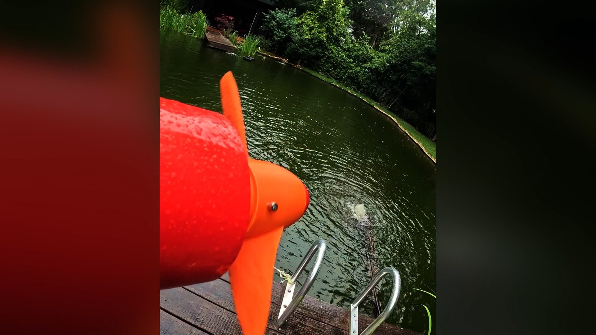
Check out the video below for the Complete build and maiden voyage.
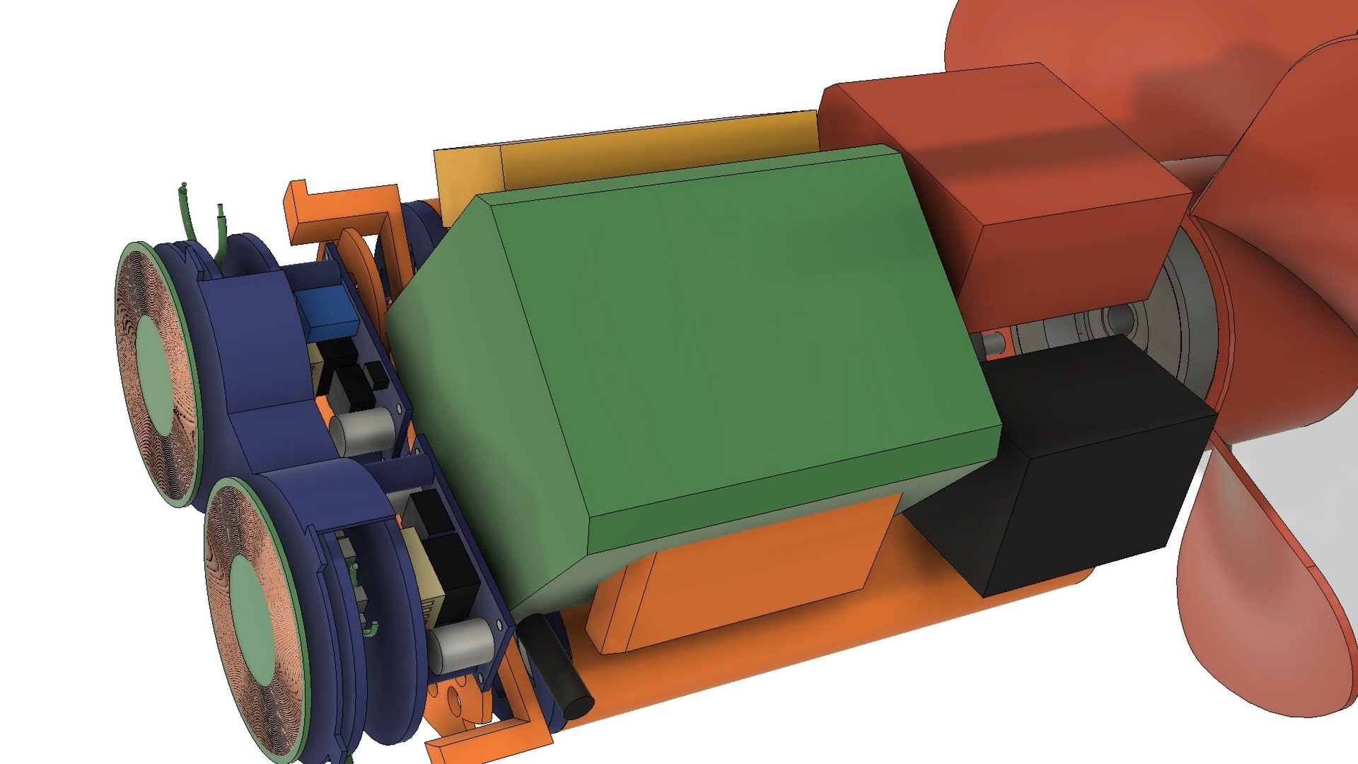
Subsystem Layout and Assembly 🤖
The biggest challenge was fitting everything inside the hull. There was no margin for error. I had to design a layout where each subsystem — the custom battery pack, the wireless charging coils, the motor, and the control electronics — fit together like a puzzle. The custom battery pack, in a 2x4 cell arrangement, was key here. It wrapped neatly around the drive motor and served as a central "scaffolding" point for all the other components. Custom-designed standoffs and mounting tabs were integrated into the hull's internal structure to ensure each part could be accurately positioned and secured during the print.
The Print-in-Place Process: A High-Stakes Assembly 😲
The final print was a nerve-wracking, 14 hour affair . The plan was to pause the print at specific layers to insert the "super widgets" and then resume printing.
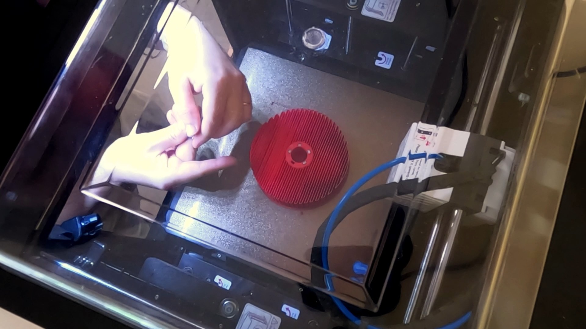
- Embedding the Magnetic Gear's Concentrator: The first pause was to embed the iron bars that form the field concentrator layer of the magnetic gear. This was a relatively simple step, requiring a bit of glue to secure the bars in place.
![]()
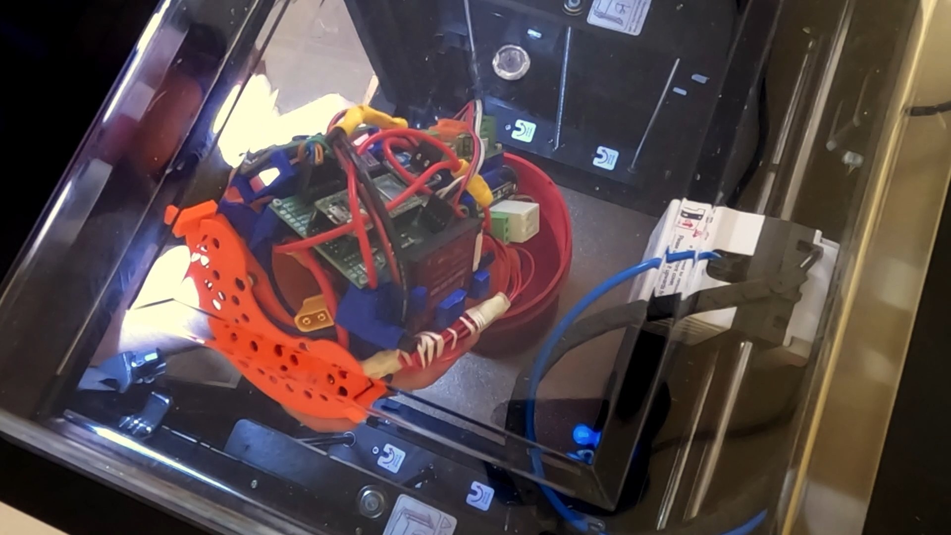
- Inserting the Drive System: The next pause was for the largest component: the complete drive system, including the motor and internal rotor. I had designed orange tabs on the drive system to mate with the hull's walls, ensuring perfect orientation. As I lowered it in, the weight of this massive component slightly lowered the print bed due to elasticity in the Z-axis belt. I had to manually adjust the Z-offset by 0.3mm to prevent the nozzle from hitting the newly inserted part and causing a print failure.
![]()
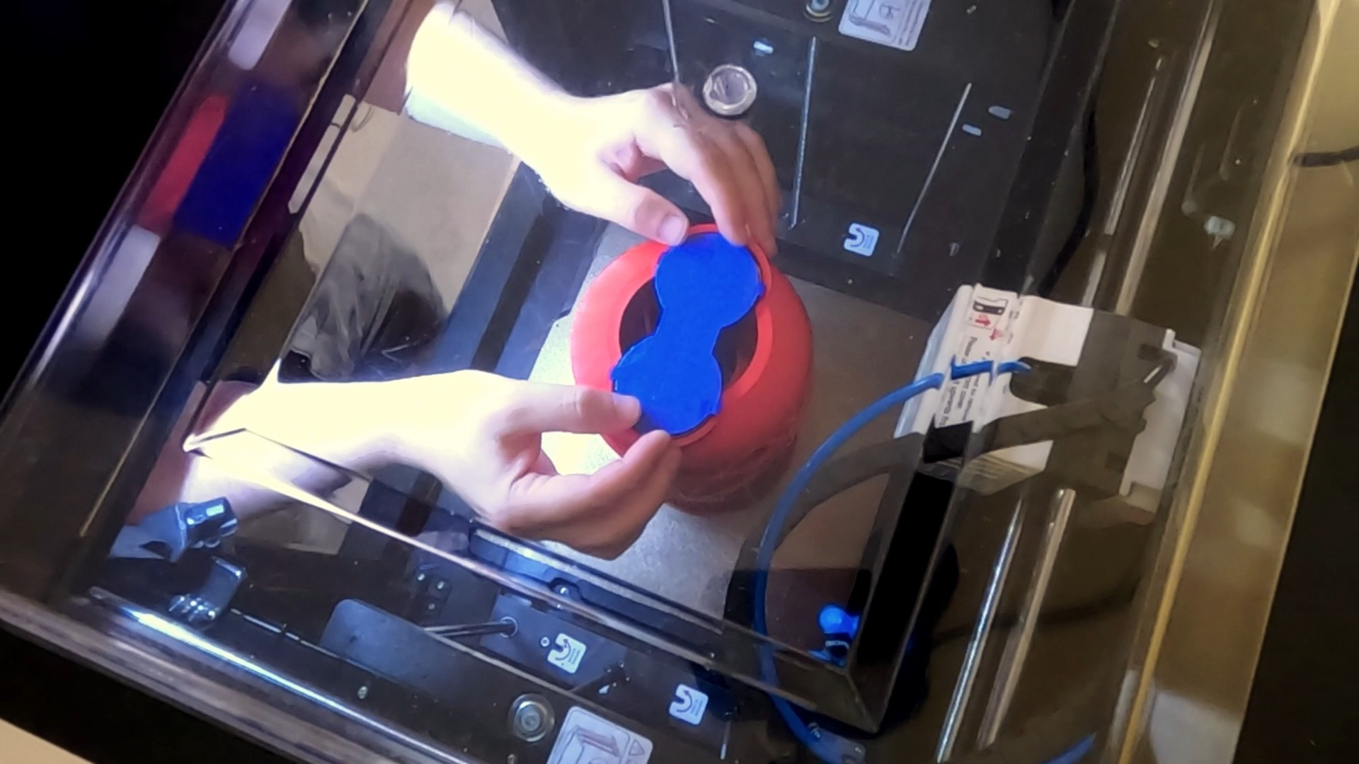
- Adding the Wireless Charging Coils: The final pause was for the wireless charging assembly. I connected it to the battery, lined it up with its tabs, and tacked it in place. Again, a small Z-offset adjustment was necessary to keep the print running smoothly.
![]()
The print finished successfully, leaving me with a completed hull and all the internal systems encapsulated. The last step was to coat the exterior in epoxy, and the impossible print-in-place sea scooter was finally a reality.
Discussions
Become a Hackaday.io Member
Create an account to leave a comment. Already have an account? Log In.