 Ben
BenIn this update I've been looking at the non-contact drive system for the propeller. where I have combined a non-contact drive system that incorporates reduction gear box, known as a magnetic gear, to better match the motor with the propeller.
If you are interested complete details of this part of the build process is documented in the below video
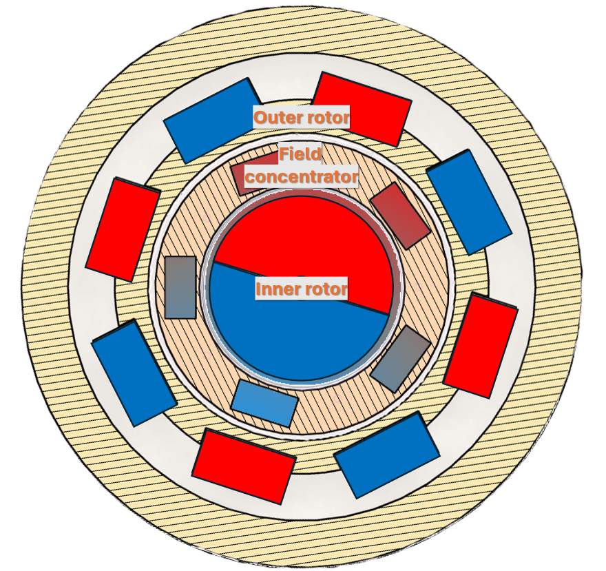
A magnetic gear is made up of three components a inner rotor, field concentrator and outer rotor. As the inner rotor rotates the outer magnetic rotor rotates in the opposite direction by an amount that is equal to the ratio of the outer to inner number of magnetic pole pairs. In this design the ratio is 4:1.
If you’re interested in more details of the construction of the magnetic gear, how it works and performs check out video below.
Incorporating the magnetic gear into the hull.
For this design to work I needed to be able to incorporate the field concentrator layer that contains 5 soft iron field concentrators into the wall of the hull that I need to be able to printed together with the hull in one go.
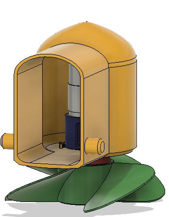
The simplest setup I could come up with to test this integrated magnetic gear design was to create an access port in the hull and add a motor and motor mount. Powering the motor remotely using an external power supply.
I also need to cut some 5mm thick strips of low carbon iron to use as the magnetic concentrators. To make this easy for myself I decided to build cross cutting jig for my DeWalt mini grinder.
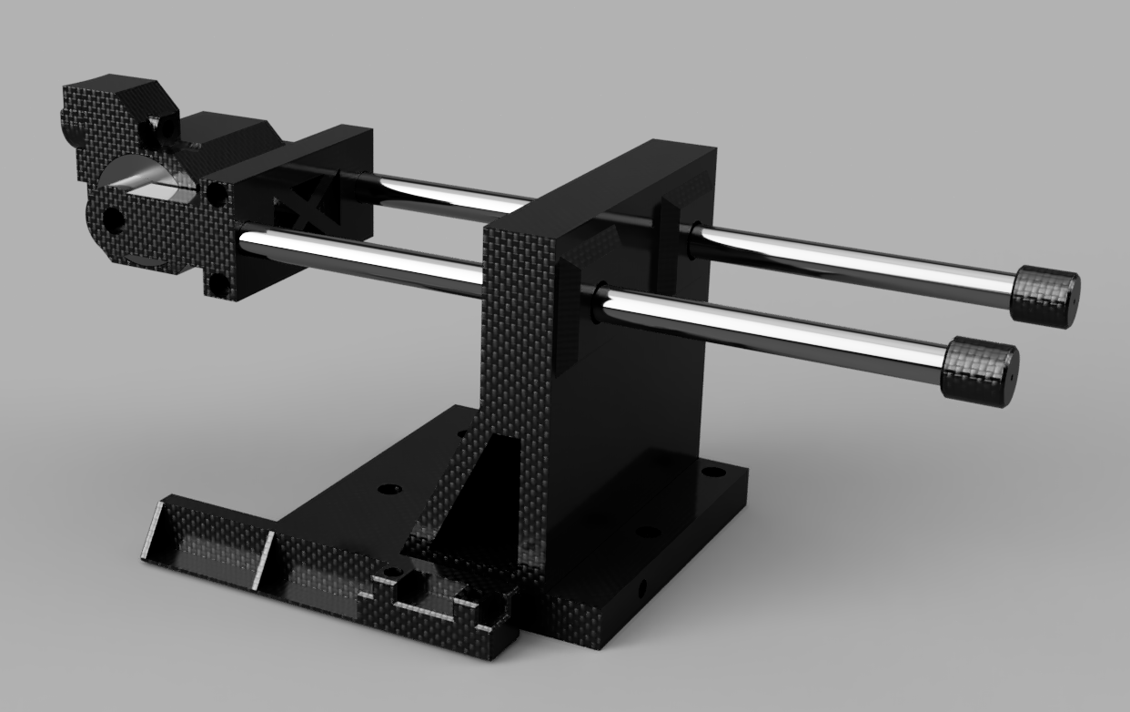
This design also incorporates a fence to make cutting the same dimension easy. As you can see it does the job fairly well. The only slight addition worth incorporating in to add a bit of metal angle to the fence and square edge that are in contact with the part being cut to prevent the plastic from melting.
If you want to see how the cross cutting jig is designed and put together check out the video I made on it below.
I then glued the shroud on to the hull and then coated the surface in epoxy. This time I tried some readily available 5 minute epoxy that you can get from the local hardware store rather than flexible epoxy as I’m not expecting there to be much elastic deformation of the plastic this time around compared with the pressure testing video and it’s much, much quicker to cure.
only thing left to do was to cut out the plastic window and make some holes to pass though the power cable and attach it to the hull and we are good to start testing.
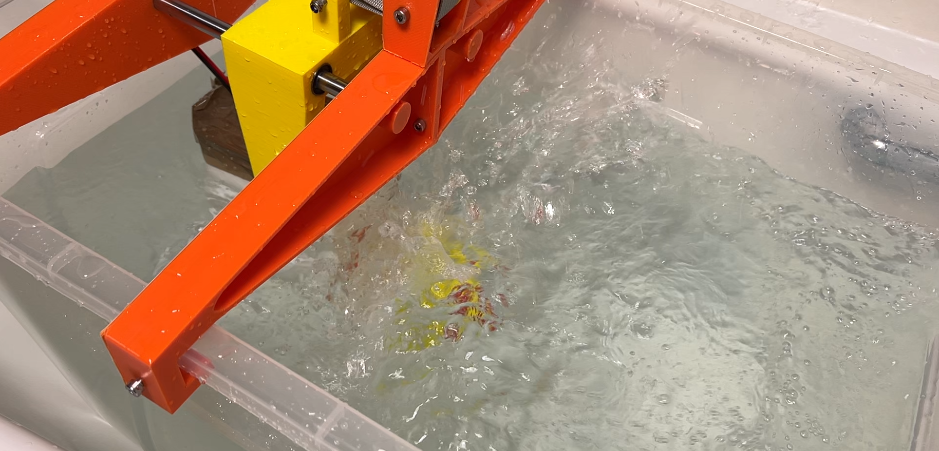
Testing rig design
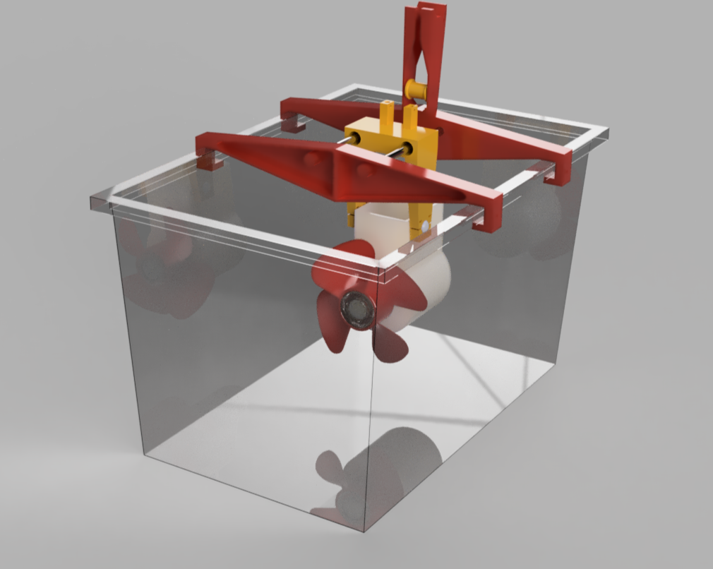
I need some sort of test rig to measure how much thrust the test hull propeller combo actually produces. So I decided to take the biggest plastic box I could find add a gantry and sled to it and attach the test hull underneath it. That way I can constrain the motion to one dimension to measure static thrust. The only other piece I needed was to actually measure the thrust. I could buy a load cell, calibrate it, attach it to a micro controller and some sort of display. Or I could just repurpose a luggage scale that I have which has a resolution of 10 grams or 0.1 newtons which should do the job. Just needed to add a pully to ensure to transfer the force from horizontal to vertical so that I could read the display and keep it nice and dry.
Propellers to test
I decided to test 4 contrasting designs for propellers to see which is the best match. These designs where some of the top ranking prop designs for the rctestflight propeller competition that was run in the summer. Thanks to rctestflight and the participants for making the designs available. If you’re interested in the detailed test of how these and a whole bunch of other propellers performed then you should definitely take a look at rctestflight’s channel and the final competition video.
Lets print out the props.
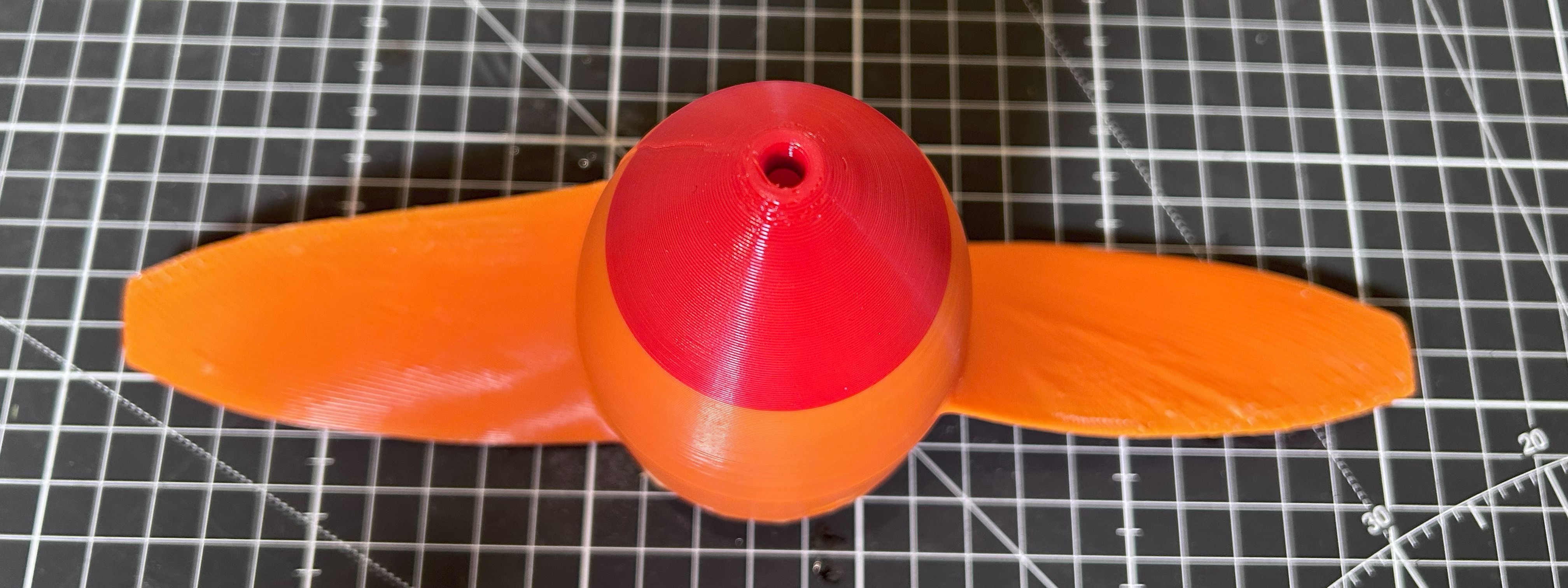
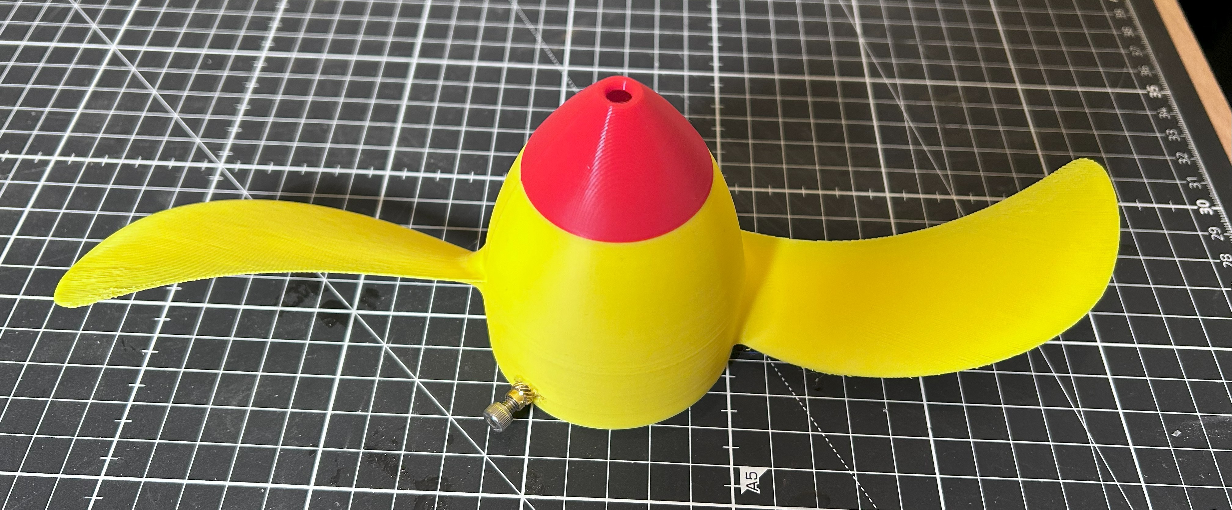
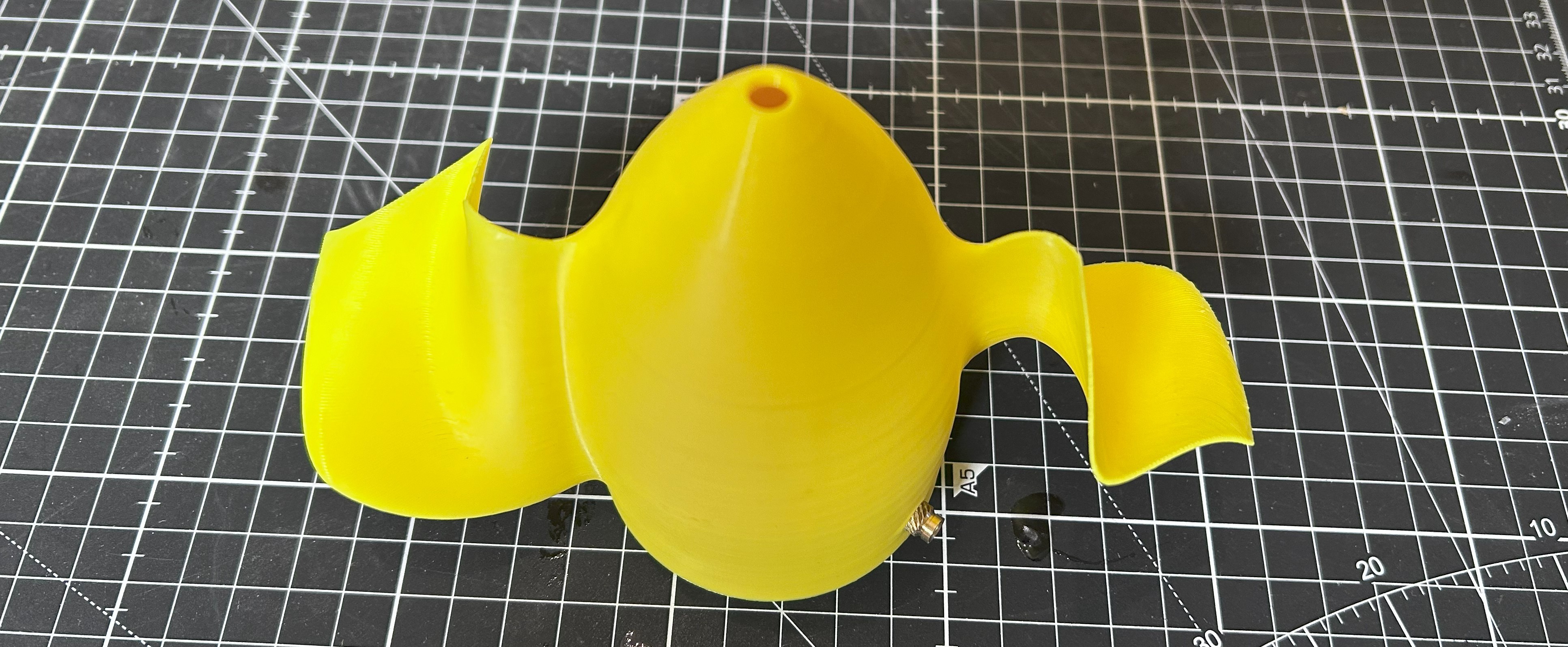

I was particularly interested to see how this one does as toroidal blades are supposed to be much quieter. For reach test I set the power supply to 24 volts and ramp up the current in 0.1 Amp increments from around 1.5-2 A to around 4 Amps.
I've gone though the out come of all the testing in the video at the top of this log entry post!
For the sea scooter design I’m actually leaning towards the toroidal propeller as it seemed the most stable, was the quietest by a mile and had the second highest max power output. It was also printed with the 0.8mm nozzle so the printed surface was very rough, so plenty of room for improvement there. Definitely scope for a second round of testing with smaller props that have also been made smooth. I wouldn’t be surprised if we can eek at least another 10% of thrust.
Discussions
Become a Hackaday.io Member
Create an account to leave a comment. Already have an account? Log In.