 Ben
BenWhat is the control system
So I've been continuing to focus on meeting the second design constraint . Working out how to wirelessly control the sea scooter…. underwater.
if your interested in the detail of this phase of the project then you might want to check out the video below that goes though it all
I've broken this down into 3 subsystems.
1 - The master on off switch or ‘key’. Which isolates the power source from the rest of the system. Reducing the passive current draw when the sea scooter is of as well as providing an emergency off button that is triggered in the event the sea scooter gets out of control, say you let go of it while underwater
2 – the throttle and axillary function to make the sea scooter change spend and trigger any other auxiliary functions that we might want to do periodically such as synchronising the sea scooter with a base station or running a special test program.
3 - the sea scooters ‘brain’ or central control system that takes in inputs and concerts these to output signals to control other systems like the motor.

Why can we just use Bluetooth or wifi..
When someone say’s that they want to make something wireless the first thing that comes to mind is why not use wifi or Bluetooth to achieve this. I mean they are pretty main stream technologies and seem to be integrated into just about anything.
the first thing to note about WiFi and Bluetooth is that these both work at 2.4GHz and higher frequency, which is the same as a microwave oven. This is because it’s a frequency that water is very good at absorbing and turning this into heat.
So when you try to send a Wi-Fi or Bluetooth signal through water, which is often about ten thousand times weaker than your microwave oven the water molecules almost immediately absorb this radiation and converts it into heat. Not very useful.
So if you work it though Wi-Fi and Bluetooth have an theoretical range of a few of millimetres though water. And as everyone I’m sure knows trying to use wifi or Bluetooth at the extreme of it’s range is often rather flaky and not something you can particularly count on.
So I've gone for something a little different and once again turn to the power of magnets to save the day. As interestingly the magnetic permeability of water is almost the exactly the same as air. So I've designed a control system that can sense magnetic fields above a certain threshold at a particular point in space so that I can transmit the intention to switch a button or increase a throttle.
Sensing magnetic fields is of course something that is not a new idea and there are quite a few ways to achieve it. Two popular, simple and well proven methods are firstly using a reed switch. Which acts like a magnetic switch that closes when a magnetic field is near . The second method uses a hall sensor to sense the strength of the local magnetic field.
Both sensors have their advantages.
The reed switch is super simple but only giving binary feedback of whether a magnetic field above a certain threshold is nearby, but consequently fairly robust to changes in the local magnetic field due to other sources of magnetism such as the motor, magnetic gearbox even the earths magnetic field.
While the hall sensor can sense the size of the magnetic field as well but this requires more complex electronics and often benefits from being connected to a microcontroller to read the output from the sensor and decide what to do with the signal. Hall sensor are much more sensitive than reed switches, which is great, but this also makes them more susceptible to magnetic noise from other sources of magnetism that are in the local area.
On this basis I’m going to for now at least make the master on off switch a reed switch. As I want it to activate independently of any other electronics and have a high threshold for being affected by other changes in the local magnetic field to maximise it’s reliability.
For the throttle and auxiliary function control. I actually tried both reed switches and hall sensors and ended up for now at least sticking to one based on reed switches. If you are interested I've included the details of why, backed up with some testing results, in the main video at the top of the post.
The control system design
Right so we’ve got our three subsystems, lets start to flesh the design out a bit.
Lets start with the sea scooter brain. – we’re going to need a simple computer, lets use a microcontroller as the brain. In addition to the two other input control systems we’ll need to out put a signal to drive the motor, to help with this we’ll need a motor controller that can drive the high voltage DC motor which in turn drives the propeller.
If this build goes to plan we’re going to end up with a hermetically sealed chamber it’s going to be important to monitor what the environment of the chamber is during operation. Specifically I think it’s sensible to monitor temperature to check that heat is able to get out of the system quick enough, the humidity to check it’s not leaking and the pressure of the chamber to check that it’s not going to pop and also as an indirect measure of how air tight it is when it goes under water and whether their might be a slow leak of some kind. Lets call this an environmental sensor.
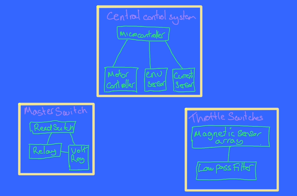
In addition I mentioned in the previous Hackaday Log post that when we add too much torque though the magnetic gear it looses synchronisation. And this synchronisation loss seems to correspond to a fairly consistent current draw from the power source. I therefore also need a current sensor to monitor how close the magnetic gear is to it’s limit as well as detect if synchronisation is lost so that the motor can back off and let the gear regain synchronisation.
For the master switch sub assembly as well as the magnet sensing reed switch I've added a relay that it can control to handle the larger current that the master switch will need to handle and to ensure the master switch is able to function on it’s own we’ll also need a voltage regulator just for the master switch sub system that can work off the raw 24 volts battery supply and step this down a more civilised 5 volts to drive the relay.
For the throttle and auxiliary sub system were going to want to ensure the signals that are coming out if the subsystem are as reliable and accurate as possible so lets add a filter to remove as much of the unwanted noise that could be created by the environment that the magnetic sensors or switches are in. As a first go i've added a low pass filter to the output signal from these sensors to filter out the high frequency sources of noise and only measure the relatively slowly changing states that would correspond with say pushing a throttle leaver.
Ok so I know logically what I want to build lets see what this looks like in terms of electronic components on the bread board .
Bread board
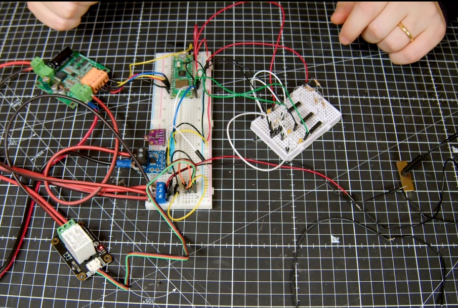
For the brain I’m using a Raspberry Pi Pico W. this is connected to a bme680 environmental sensor and ina260 current sensor via an I2C bus.
The master switch uses a waterproof reed switch connected to a L7805 5 V regulator steps down the 24 v raw battery supply to drive a 15 amp relay.
For the motor controller I’m using a 15 amp single channel motor controller that can handle 36 volts. Usefully it also has a 5v output that I can use to power the microcontroller and all the other low voltage circuits. You can see that the current sensor is inserted between the motor controller and motor and you might be able to make out that it’s sensing the low side current i.e. on the ground side rather than the high side as high voltage PWM drive signal produces far too much electronic noise to be operated in the vicinity of the low voltage logic. As soon as I tried to measure the current using the high side configuration above about 15 volts the sensor stopped working.
The throttle and axillary control system design based on reed switches. uses a series of equally spaced reed switches that each incorporate an Resistor and capacitor to create an RC low pass filter. As the magnet passes over the reed switch it is activated. It’s actually possible to have more than one reed switch activated at any one time so allowing us to interpolate the magnets position as well.
For approach two that uses hall sensors I’ve mounted two hall sensors on the PCB so that they are in the same plane. As the magnet moves over them the relative magnetic field that is sensed should change fairly repeatably.
It will be interesting to see how they compare.
Proto board
So you can see that the bread board seems to be wired up correctly and working as expected. Lets transfer this onto proto boards so that I can integrate them into the test hull.
Much soldering later.


Design and build the casing.
Right so next step was to work out how to fit all these electronics into the test hull so I could do some in water testing.
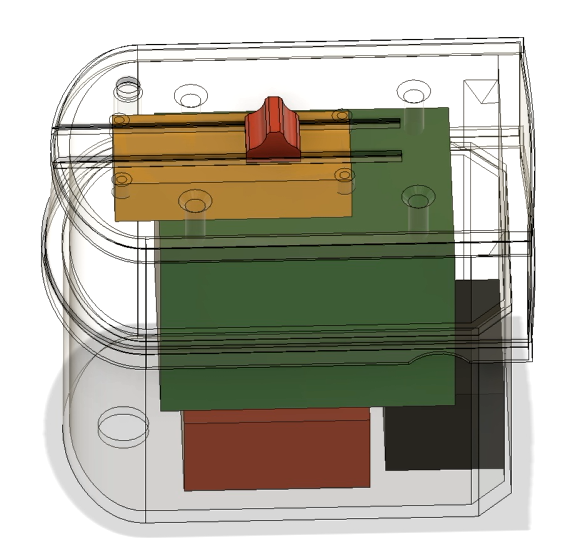
For this I created a case that fits on top of the test hull and can double as a replacement for the polycarbonate lid. I added add some rough bocks for each of the pcb’s in the CAD model to make sure we can fit everything inside. On the lid I’ve added some tracks to mount a slider that will hold a magnet and test the throttle control behaviour.
I’ve also included a mounting point for the master reed switch to test that too.
Lets print it out.
Assemble the electronics
I added some threaded inserts to make mounting the pcb’s easier
And made this as transparent as possible with a bit of sanding and a coat or two of clear coat.
Next lets mount the pcb’s and wire them up…..
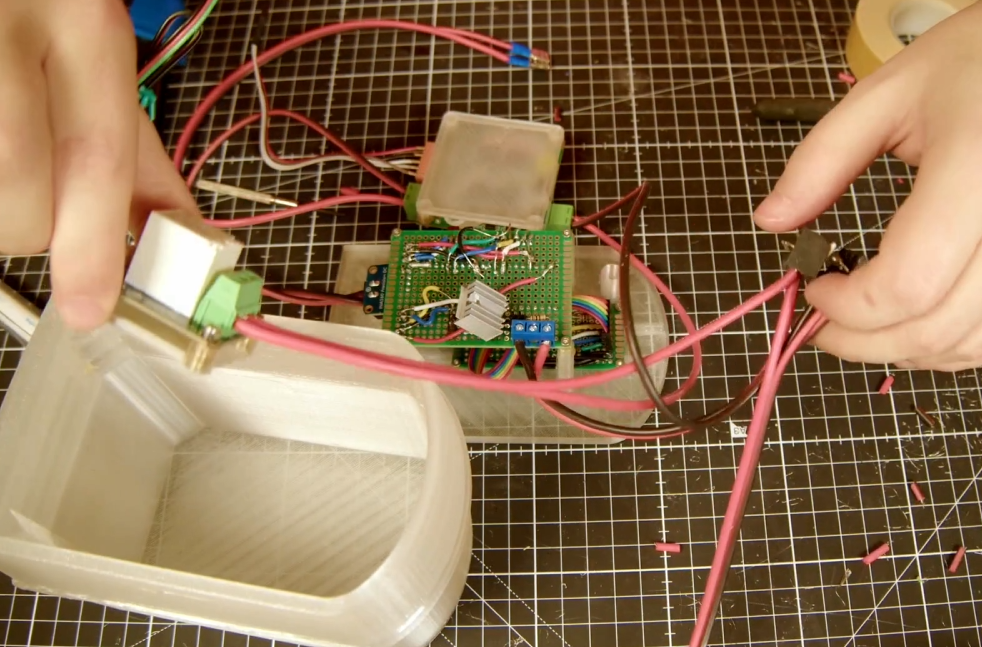
That was quite a bit of work but we got there in the end.

The Code
If you’re thinking that there must be quite a bit of code required to control the Pico, you’d be right. I’ve tried to keep it as simple as possible by writing it all in micropython and arranging it into a few modules.

In summary there is a main script that runs on boot and calls on the other modules as part of the script. These are for the INA260 and BME680 current and Environmental sensor communication modules. Seascooter and sea scooter_test modules contains general functions that are required for the sea scooter background operation like system logging and calculating throttle response based on the magnetic sensors. And OTA and sendmqtt are all about getting data in and out off the pico.
Rather than go through the detail of the code line by line here I’ve included a link to the git repository in a free member Patroen post here if you are interested in the detail.
The only bit that I’ll mention here is that for testing purposes I though it might be a good idea to create a web app to monitor the status of the scooter during testing that I could access from my phone. I’ll talk though the specifics of the final design of this in the next video, as the current solution is really geared around getting realtime data out of the sea scooter for live, partially submerged testing. Rather than the final solution which will have different connectivity constraints.
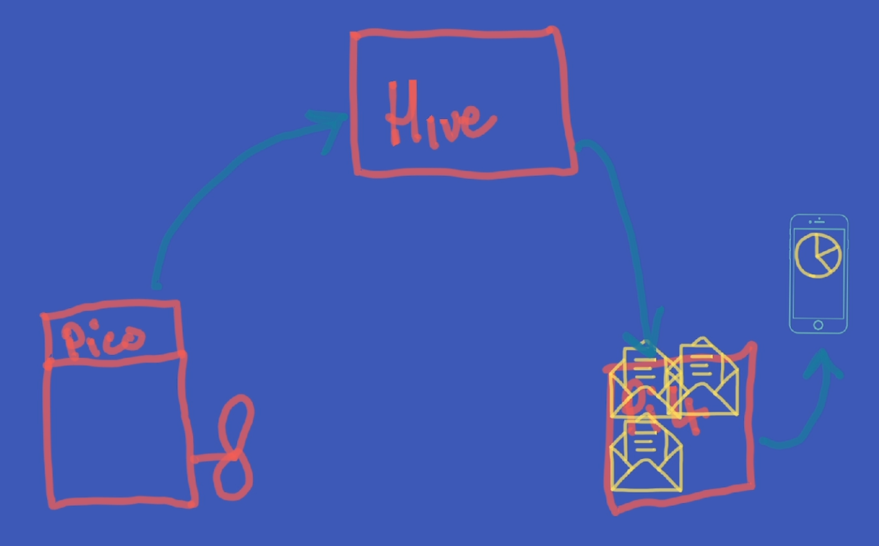
But in big handfuls the sendmqtt script on the Pico W, uploads, or publishes, every quarter of a second the complete state of all the sea scooter sensors as a set of messages with different tags, via WiFi, to something called a message broker, for this I’m using a free cloud based one called HiveMQ. These messages are then stored in different topic ques based on the tags that they arrive with. I then built a simple application using the open access Node Red platform, installed on a Raspberry PI 4, that subscribes to these topics, collects these messages from the message broker and displays this information on some real time dashboards that you can view via a web browser.
Because it’s a locally hosted website I can make it look like an app on my phone and connect directly to it to monitor the sensors in real time and plot the values over time.
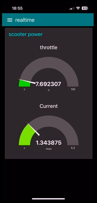
Here you can see the Realtime throttle value and current value from the web app on my phone.
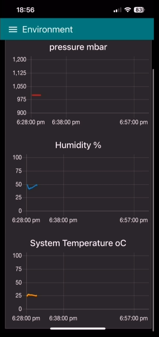
As well as the pressure temperature and humidity of the sea scooter over time.
Pretty neat eh.
In bath testing
Before i started ting I thought I might be worth iterating on the propeller design a bit and trying a few of the improvements that you popped down in the comments in the last video.
Firstly I took the three best designs from the last video and make sure that they are all the same scale as the original design intended them to be. I then flipped all the designs so that the they all have the same pitch direction so I don’t get caught out like I did last time. Next I printed them all using the smallest nozzle I have, which is 0.4 mm and the have a bit of a go at smoothing the surface and edges using sandpaper first…. Followed by a couple of coats of clear coat.

These small diameter props SHOULD be able to output more power with less torque required, which is good for the magnetic gear. Also the smaller diameter should ensure that the tips stay submerged during the testing.
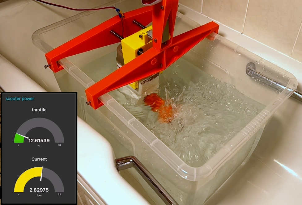
Well that’s the theory anyway… check out the full video below to see how the electronics and props preform using the same test rig that we used last time. as it didn't quite go to plan.
But at least all the electronics seemed to be working as expected :-)!!
Discussions
Become a Hackaday.io Member
Create an account to leave a comment. Already have an account? Log In.