 Ben
BenIn this post It’s time to focus on the wireless charging and battery system of the sea scooter.
If you are interested the below video documents this stage of the build. So please do check it out!
What is the power system
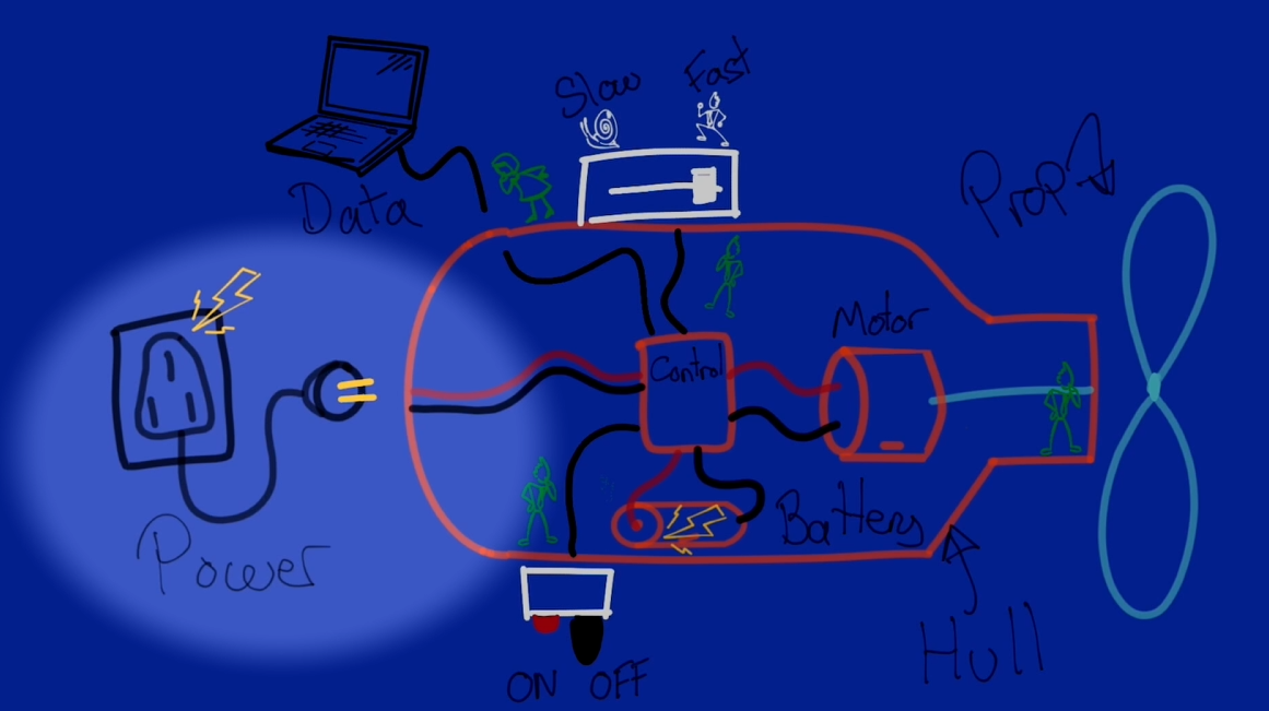
I've broken the power system down into 2 main subsystems.
1 – The power storage subsystem. Comprising of a battery pack and battery management system.
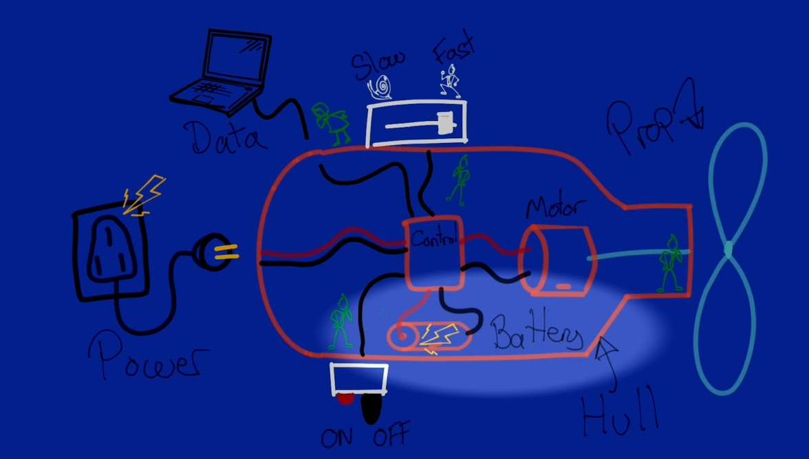
2 – The wireless charging subsystem. All about efficiently getting enough power at the right voltage though the hull wirelessly to charge the batteries in a reasonable time scale.
Designing the power management subsystem
I first takeled the design of the power management system as this will have a knock on impact to the wireless charging subsystem design. The first decision was what voltage and maximum current I want the system to run at. If you’ve followed the previous instalments of the build you might know the answer.
Quite early on in the build I decided to design the system to run at around 24 volts with a maximum 15 Amps current draw on the basis of the characteristics of the motor and it being still a safe voltage to work with.
To calculate the Watt-hours capacity. I’m going to approximate the power consumption as the maximum expected power consumption of the Motor. Following the results of the magnetic gear propeller testing I arrived at a max current draw before the magnetic gear stalled at around 4 amps. So I’m going to work on the basis that the max average power consumption of the sea scooter will be 4 amps. So the total power consumption would be voltage times current so 24 times 4. Lets call it 100w.
The next question is what is the minimum time I want the scooter to run for on a full charge?
I think anything under 30 mins would be rather frustrating so i've picked that as the absolute minimum run time. Which if it’s running flat out at 100w would consume. 100 times 0.5 which is 50 Watt hours of capacity.
I've decided to design my own battery pack that will snugly fit into the hull. It will be a fun mini project on it’s own.
Right so given that I’m making my own battery pack the first thing to decide was what battery chemistry do I want to use. As this would affect the way that I’d have to wire the battery up, volume and storage capacity, also the charging circuit.
To cut a long story short I ended up deciding on LiFePO4. Principle on the basis of high energy density. High discharge rate. one, if not the most stable of the mainstream Li-ion battery chemistries. Modular form factor. And..well.. I found a job lot available at a really good price on eBay. :-)
This is what a single LiFePO4 cell looks like.
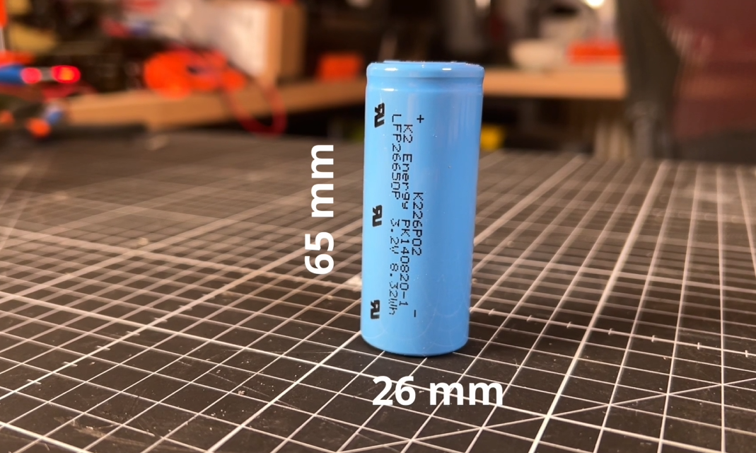
There are a few common form factors you can by the most common is called a 18650. Which means that it is has an 18mm diameter and 65 mm long. This one is actually a 26650 which, as you've probably guessed, it means it’s got a larger diameter of 26mm and a length of 65mm. These batteries have a nominal voltage of 3.2 v. Which is importantly is different to the 3.7 volts per cell your probably used to if own a LiPo battery for an RC car or plane. These one’s have a capacity of 2.5 Ah and a somewhat unnecessarily high discharge rate rating of 42 A. Apparently they were originally spec to go in an EV car battery. I think I paid around $3 per battery.
Ok so I’ll need a battery that runs at around 24 volts.
We can increase the voltage though the magic of simply connecting the batteries in series
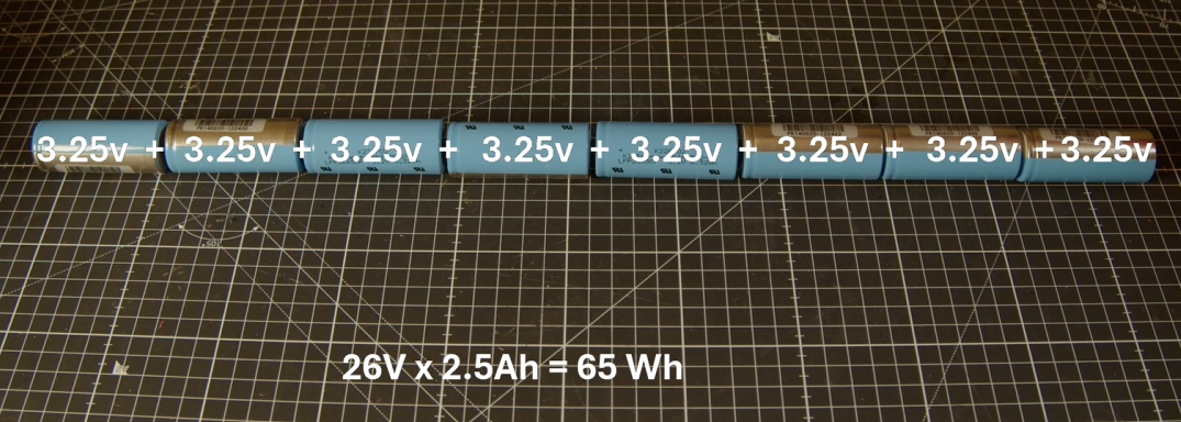
Ok so 8 cells is the magic number to get us over 24 volts. So this battery configuration would give us 26 volts times 2.5 amp hours equals 65 Wh of energy storage capacity. Which should give us a minimum of 40 minutes run time under normal conditions, so more than the 30 min minimum run time I was aiming for.
So it looks like this battery pack that I will need to build will need to be wired as an 8S 1P battery pack or in other words an 8 cells in series and 1 set of cells in parallel.
One of the down sides to Li ion batteries is that they are fairly fussy about what voltage they are being charged at and discharged to. If you go outside of this range they start degrading rapidly and in extreme cases might case the battery to become unstable and even catch fire.
To ensure that each and every battery cell is being maintained within the required voltage range when operating a key component of any Liion battery is some sort of battery management system, often simply referred to as a BMS.
After searching around I eventually decided to go for one made by the relatively well known Chinese company called Daily BMS that sits towards the bottom end of the market, but cater for just about all battery configurations and most importantly LiFeO4 chemistry. As the min and max voltage range is 2.3v to 3.65v compared to most other Li ion chemistries you’ll typically see that are 2.7v to 4.25v.
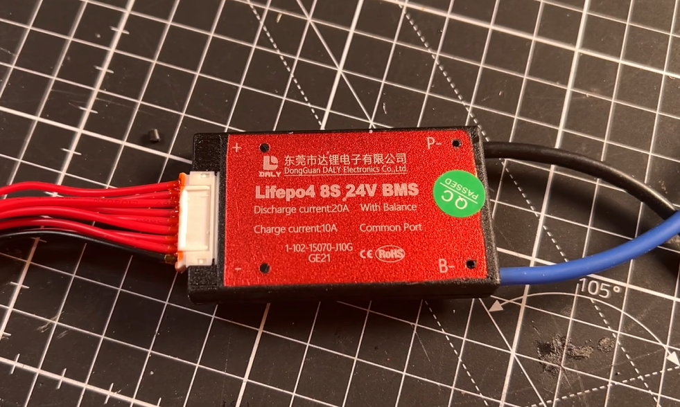
This one is an 8S 24v, well i've already mentioned that it’s really more like 26v nominal and if we want to charge it to 100% then we’ll actually need to supply 29.2 v! It’s spec’d for 20 A continuous discharge and 10 amps charging which should be plenty for this system. And it apparently also have a sort of last resort over current protection for both charging and discharging current limits.
You can see that it comes with quite a few wires. That’s because each cell-string in series needs to have its voltage individually monitored. Since I only have one cell in each string this makes it a little easier.
Designing the enclosure.
Great so we know how the battery pack needs to be wired now lets design something that will fit snugly into the sea scooter hull, in the gap between the motor and the hull. I think 2 cells by 4 should be pretty efficient packing so will go for a crescent shaped outer battery holder, that has a base plate to followed by 4 battery’s then a spacer between the cell layers so that I can attach the BMS monitoring cables, then another 4 cells and finally a lid. I think that looks pretty compact.

Assembling the battery pack.
I first added some battery terminals to the blue top middle and bottom parts. Then solder on some thick gauge wire to create a path from the first cell to the last to give us our 8 cells in series. Then solder on the BMS cell monitoring wires to each of the positive terminals of the cells plus an initial ground. Then solder on some thick gauge wires to the Positive and Negative terminals.
The BMS then sits between the negative terminal of the battery and the negative wire of the external charging or discharging systems. With the positive battery connected straight to the external system.
Ok so on to the Wireless charging subsystem
Great so now we know what the vital statistics for voltage, current and capacity parameters for the power management system to design and source a wireless charging system to feed it.
After doing a bit of research I think a resonant inductively coupled wireless charging system should give the best bang for my bucks. Very few that I found actually even quote an output current. But this one seemed to be the best output power to size to cost balance. Apparently It’s got an input of 24 v and an output of 12 v delivering up to 2 Amps. Which would give me up to 24 Watts of charging capacity.
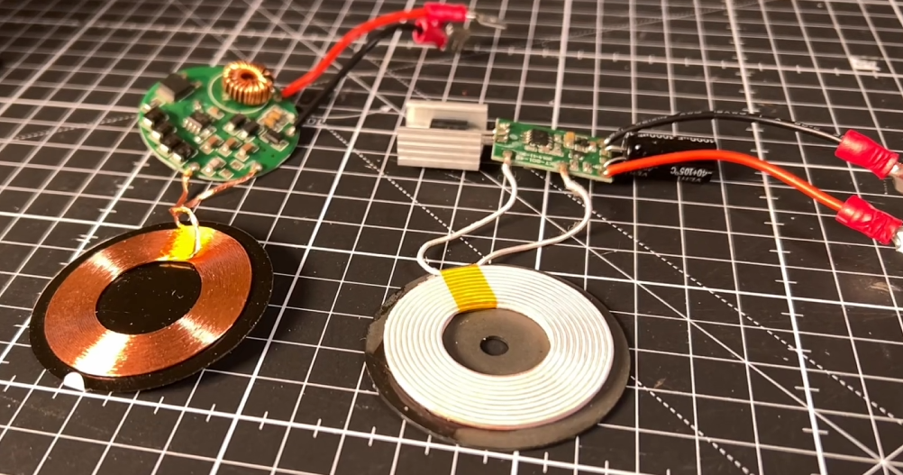
Ok now lets tackle the output voltage as we need 29.2 v to charge the batteries to 100%.
To do this I’ll add a boost converter. Which has a sole purpose to take an input voltage and step it up to a higher voltage. And I can use little blue trimmer component adjust the output voltage. I think these where about $1 each and supposedly handle 3 Amps and boost up to 35 volts.

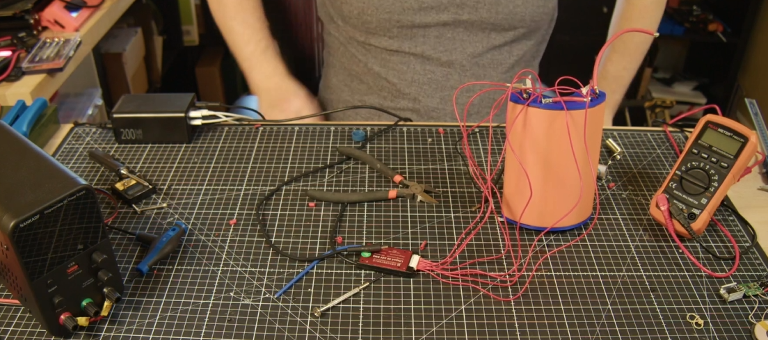
And after quite a bit of testing. I ended up settling on the below design. which uses multiple wireless charging coils. (see the video at the top of the post for details).
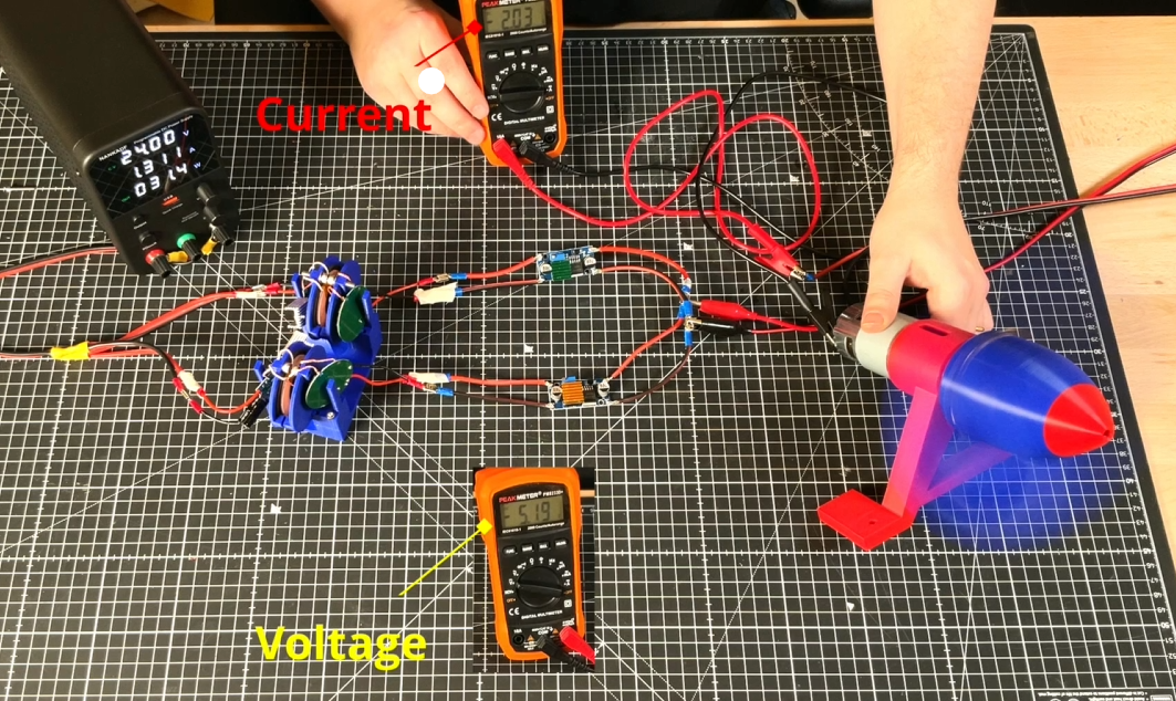
which ended up being able to charge my 26v LiFePO4 pack at 1 Amp as you can see in the below picture which should be plenty of power for this project!
I shall call that a success. :-)
If you are interested the below video documents this stage of the build. So please do check it out!
Discussions
Become a Hackaday.io Member
Create an account to leave a comment. Already have an account? Log In.