 Nicholas LaBonte
Keyboard:
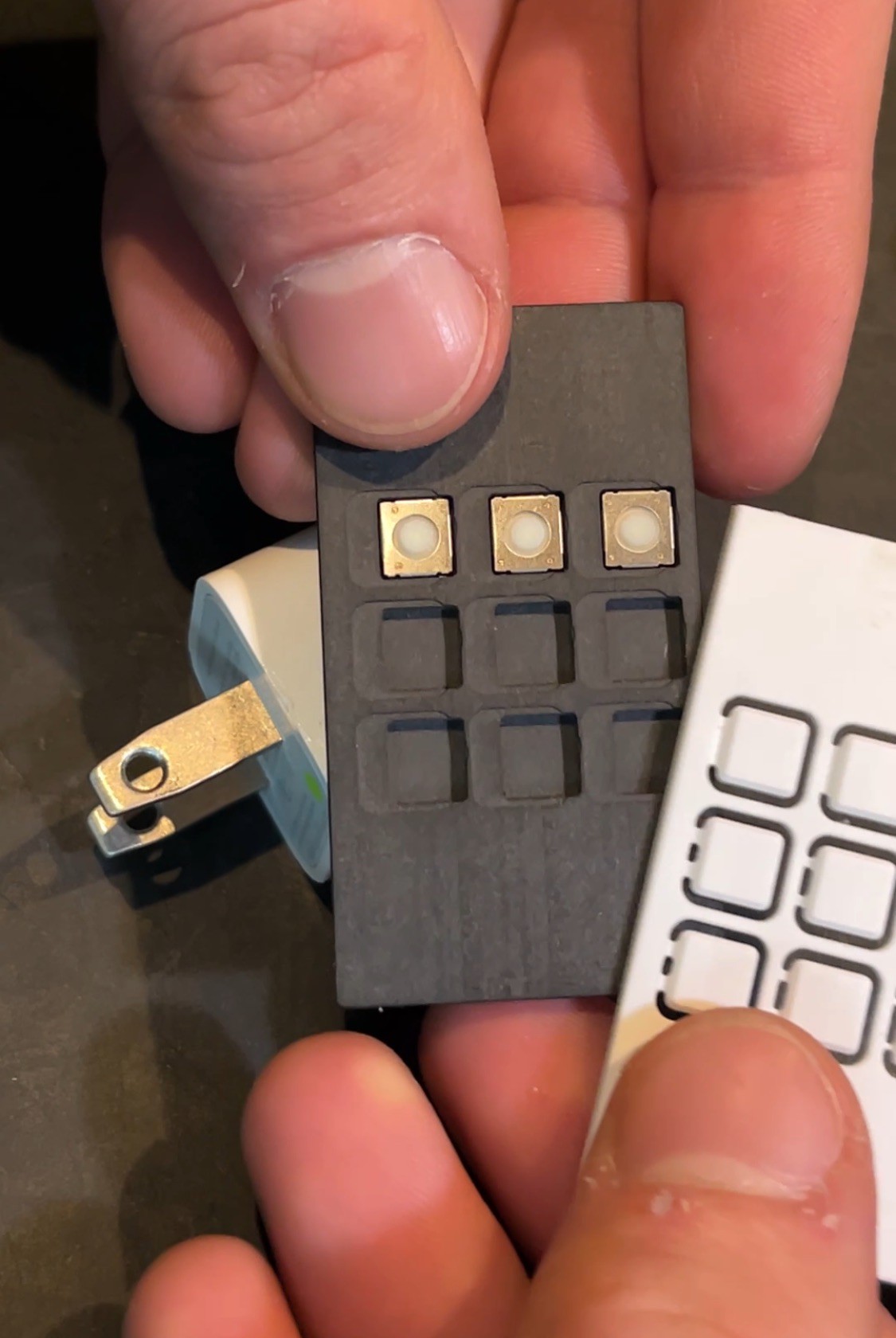
I began modeling the face plate panel and keypad in Fusion360. To help test different combinations of switch weights and keypad materials, I machined a 3x3 section of the keyboard.
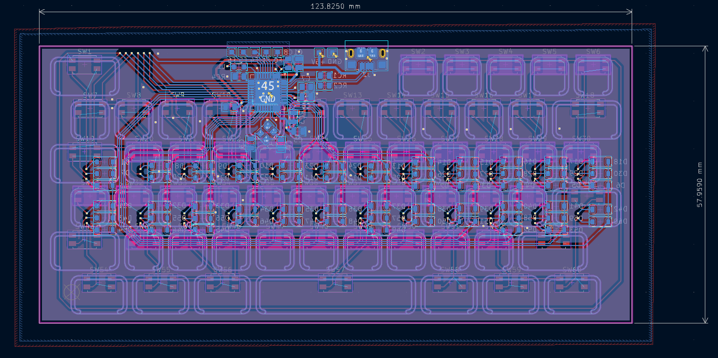
After finding a satisfactory combination, a .dxf sketch of the full keypad was imported into KiCAD and used as a guide for laying out PCB components. I placed the PCBWay order (with assembly to avoid biting off too much) and began refining the internal layout of the assembly.
Internal Layout:
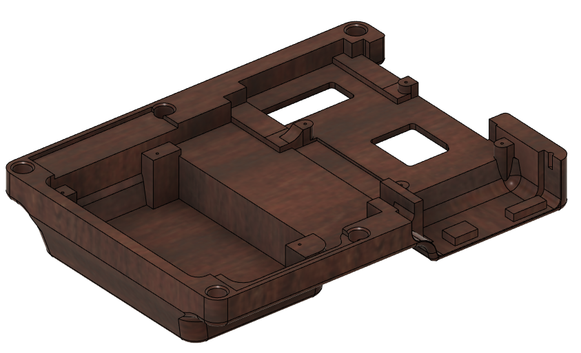
The screen and Raspberry Pi 5 would be placed back to back so I used the thinnest display I could find to minimize overall thickness. Although not a touch screen and “only” 800x480, using DSI vs. HDMI or GPIO met this goal. An RTL-SDR fit nicely beside the Pi, so including it was a no-brainer. The last major internal component is the UPS, which seems to give at least 5hrs of continuous YouTube playback. I will be doing a more structured stress test soon. Pad features and screw holes for components were included in the CAD model to help with assembly.
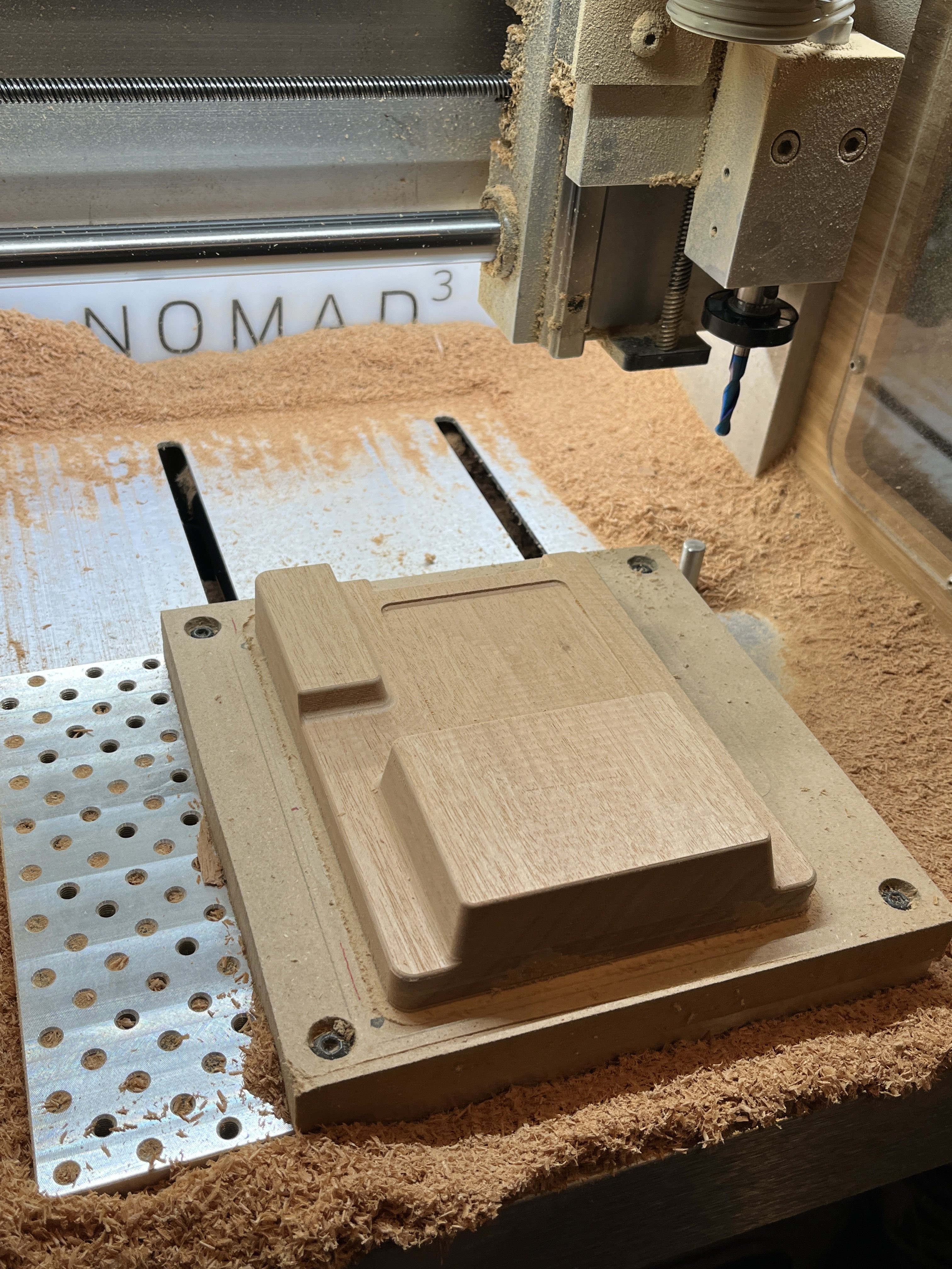
Fabrication
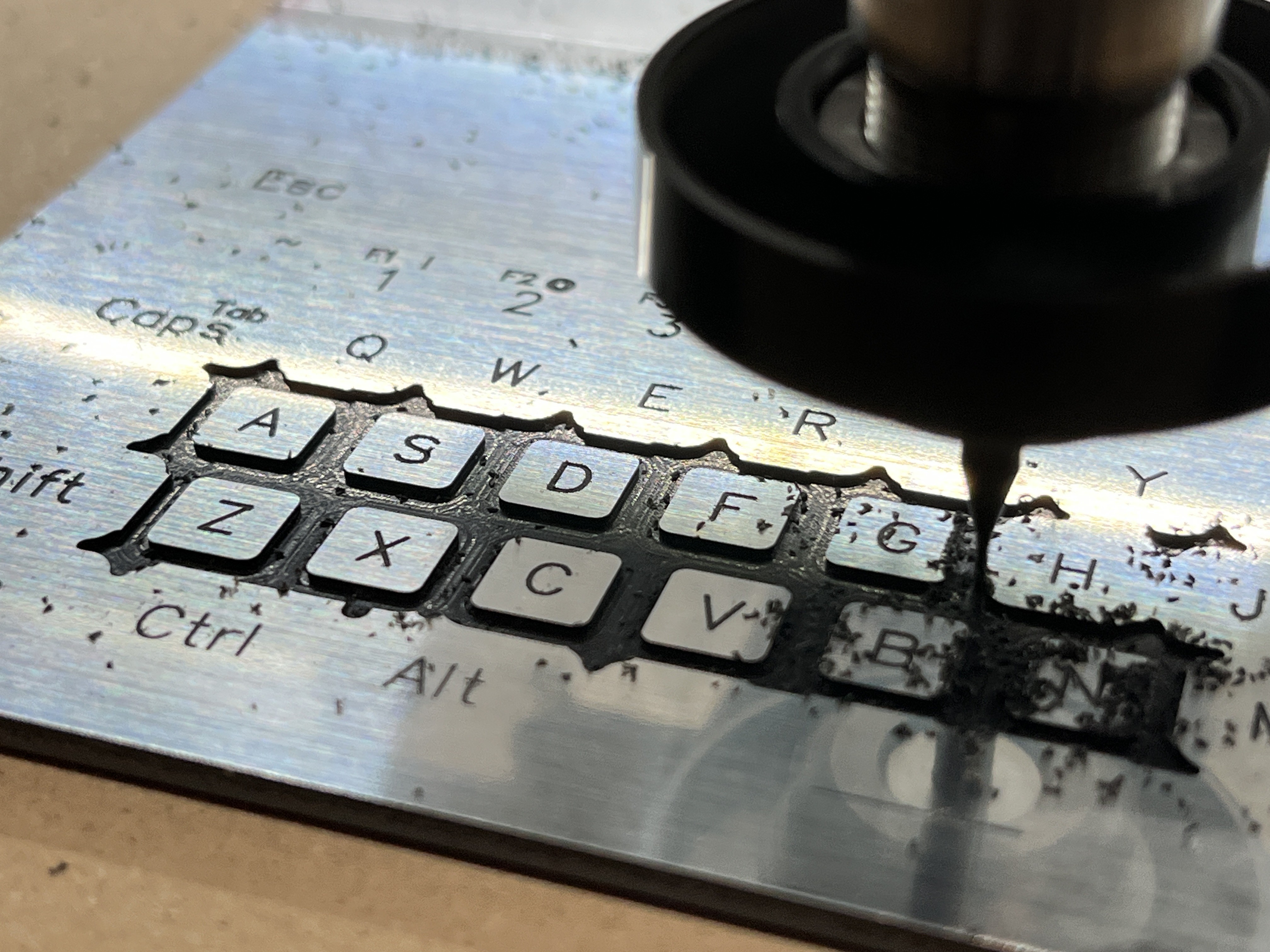
The Nomad 3 by Carbide 3D was awesome as always on this project. Machining the wood back was done with a single-flute Datron 5mm cutter, working much better than the 0.25” compression endmill that I tried. Some cheap Amazon 1/32” endmills were used to cut the slots in the bronze heatsink and keypad, and a 15 degree vee bit was used to engrave the Gravotech keypad labels.
Assembly:
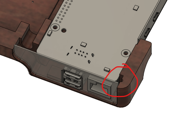
The faceplate screws (6) mate with bronze inserts that are carefully driven into the wood back while applying lots of force to avoid splitting the wood. The upper right insert is of a smaller size and is Gorilla Glued into a feature that I hand-cut with a lollipop carbide burr in a hand drill since it was an over-hung feature. Before installing the Pi, this insert could be located and glued by installing all other fasteners and reaching through the right hand I/O area.
To free up USB ports for internal use, I removed the double USB 2.0 stack by trimming the metal shielding away until there was a single piece attached to each through-hole pin. Solder wick and flux were used to remove as much solder as possible from the opposite side of the board, and finally, each pin was removed by pulling with the iron applied to the bottom side of the component. Salvaged Cat5 cable and a micro USB cable were used to connect the SDR and keyboard, respectively, to the Pi.
Firmware:
QMK configuration for handling keyboard, mouse, and mouse button functionality.
Next Steps:
-Make build video of second unit
-Add shielding for SDR
-Send I2C battery status to desktop toolbar
-Fab fan shroud