 yaluke
Software Stack
To provide the required functionality, the platform needed to support fast I/O and easy USB handling. Initial experiments with direct GPIO usage for reading encoder signals showed that signals could be partially lost during rapid rotation, as direct GPIO can only handle changes up to ~10kHz. A much better and faster option was to use the Programmable Input/Output (PIO) functionality available on the Raspberry Pi Pico.
Initially, I planned to use the simplest software option - MicroPython, but it lacked direct support for USB functionality. CircuitPython was the second candidate, but it didn't have full PIO support. Finally, I chose C++ as it offers good USB support for the Raspberry Pi Pico (TinyUSB library) as well as PIO capabilities.
I based the implementation on the hid_composite example from the TinyUSB library and removed all sub-devices from the implementation except for the generic input/output device. I completed the code with a simple class handling the TM1637-based display and an Encoder C++ class with custom PIO code for handling encoder signals.
For development, I used Microsoft Visual Studio Code with the official Raspberry Pi Pico extension (on both macOS and Windows).
List of components:
- Visual Studio Code (https://code.visualstudio.com/)
- Raspberry Pi Pico extension (https://github.com/raspberrypi/pico-vscode) (installed from extensions list in VS Code)
- Raspberry Pi Pico PIO (https://hackspace.raspberrypi.com/articles/what-is-programmable-i-o-on-raspberry-pi-pico)
- TinyUSB library (https://github.com/raspberrypi/tinyusb/blob/pico/docs/getting_started.md) (installed by RPi Pico extension as a part of Pico SDK)
- OpenSCAD (https://openscad.org/) (for designing cases)
Encoder Signal Processing
The encoder generates a two-phase orthogonal pulse signal, with 400 pulses per rotation for each phase. Decoding of this signal is performed by a PIO program (in the file encoder.pio) that waits for a rising edge on channel A, and then checks the value on channel B: for 0, IRQ 0 is generated; for 1, IRQ 1 is generated. These interrupts are handled by the Encoder C++ class: IRQ 0 decreases the rotation counter, while IRQ 1 increases it. This configuration generates 400 impulses per rotation, and the counter value needs to be multiplied by 360/400 = 0.9 to represent the value in degrees.
The precision of the measurement can be increased to 1600 pulses per rotation by adding three more PIO programs: one waiting for the falling edge on channel A, another waiting for the rising edge on channel B, and a third waiting for the falling edge on channel B.
USB Communication
The USB handling implementation is based on the hid_composite example from the TinyUSB library. All device types except generic input/output devices were removed from the original code. The implementation can be tested on a host device using two examples from the tests directory:
- test_hid.py, which uses the hid library (https://pypi.org/project/hid/)
- test_pyusb.py, which uses the pyusb library (https://pypi.org/project/pyusb/)
Build Instructions
Connections
Encoder <-> RPi Pico
- VCC [red] <-> VBus [pin 40] (5V)
- GND [black] <-> GND [e.g. pin 38]
- channel A [white] <-> GP2 [pin 4] + 10 kOhm pull-up resistor to 3V3 [pin 36]
- channel B [green] <-> GP3 [pin 5] + 10 kOhm pull-up resistor to 3V3 [pin 36]
TM1637 display <-> RPi Pico
- CLK <-> 5 [pin 7]
- DIO <-> 4 [pin 6]
- VCC <-> 3V3 [pin 36]
- GND <-> GND [e.g. pin 38]
Reset switch <-> RPi Pico
- 3V3 [pin 36]
- GP14 [pin 19]
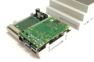
Case
Simple device cases and a plug-in case, designed using OpenSCAD, are available in the case directory on GitHub.

 Roni Bandini
 Jithin Sanal
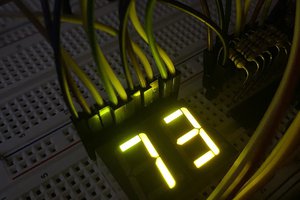
 Arkadi