Some more information about how we created the PCB panels that soldered together, form the PiDP-1's case (Cases, we have two variants...).
In the Files section, we've placed a Kicad PCB design file which turned out to work well; maybe they are interesting for other projects.
Here is the PCB set that makes up the stand-alone console version of the PiDP-1. Two sides, a top and bottom panel, and a thin panel that sits at 45 degrees at the front-bottom of the case:
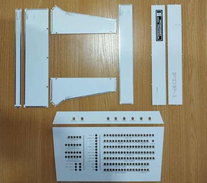
We went through a couple of months experimenting with the solder pads, the sizing of the tongue-and-groove pairs that clip one panel into another, and the fitting of the removable back panels - which are the two strips at the top right. We don't want these to be soldered in permanently, so they just are clicked in.
The '3D' solder pads need to be strong, and placed as close to the panel edge as PCB manufacturers allow. Make them too big, and a simple soldering iron will not provide enough heat to make the 3D solder connections. Make them too small, and the do not stick to the PCB well enough.
Also, the tongue-and-groove pairs that help ensure a perfect alignment required some experimentation. First though - yes, they also provide some extra strength as well, but are not really needed for that purpose as it turns out. Anyway - the problem with these pairs is their precise dimensioning. When the PCB manufacturer routes out the PCB's outline, the router bit does not always have the same diameter. We've done plenty of prototype tests by now so conclude that a 0.1mm of extra space is needed around such features (the tongue is 0.1mm smaller on either side than the groove it fits in) to give (a) a good fit and (b) will not cause trouble in extreme cases of manufacturer tolerance.
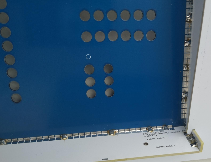
Here is the inside of the case (or frame) used for the rack-mounted PiDP-1, showing the solder points. It takes less than two seconds to do each solder spot, and we found that doing the solder spots every few cm apart already gives all the strength you want. This will hold even if you drop the case on a concrete floor - an unintended experiment.
We feel the end result is easy to build, but also looks very good from the outside. Here is a detailed shot of the base of a console PiDP-1:

You can certainly leave out most of tongue-and-groove features. The soldering alone makes the case strong enough. But it does make it a lot easier to construct the case, without having to worry about alignment issues.
Perhaps more detail than anyone wants, but we spent quite some time experimenting and if you consider PCB cases for other projects, maybe the Kicad file we put in the Files section will be of use.
Discussions
Become a Hackaday.io Member
Create an account to leave a comment. Already have an account? Log In.