Lithium ION
When talking about standalone single cell battery chargers only one popular name came into my mind that is our versatile Li-Ion/Li-Po TP4056 battery charger. Which is vastly available and has a lot of features related to battery protection. The lithium batteries are easily available in the market with proper charging solutions, but when it comes to solar changing a few microcontroller projects can be seen over the web. I want to create a standalone solar battery charger module, and luckily I found one solution at consonance CN3165, Like TP4056 Li-ion, the charge current can be set externally with a single resistor.
Onboard features include undervoltage lockout, automatic recharge, the constant current charging, the maintenance charge mode(timer termination), charge/termination indicators and battery temperature monitoring. All the modes and battery charging process is given below with all details. Big thanks to PCBWay for sponsoring the PCBs for this project! Their high-quality manufacturing and quick turnaround made this build possible.
CN3165 and it’s Features:
The CN3165 is a complete constant-current /constant voltage linear charger for single cell Li-ion and Li Polymer batteries. The device contains an on-chip power MOSFET and eliminates the need for the external sense resistor and blocking diode. An on-chip adaptive cell can adjust charging current automatically based on the output capability of input power supply, so CN3165 is ideally suited for solar powered systems.
Thermal feedback regulates the charge current to limit the die temperature during high power operation or high ambient temperature. The regulation voltage is internally fixed at 4.2V with 1% accuracy, it can also be adjusted upwards with an external resistor. The charge current can be set externally with a single resistor. When the input supply is removed, the CN3165 automatically enters a low power sleep mode , dropping the battery drain current to less than 3uA.

Features:
- Suitable for Solar-Powered System
- On-chip Power MOSFET
- No external Blocking Diode or Current Sense Resistors Required
- Preset 4.2V regulation voltage with 1% accuracy, upwards adjustable with a resistor
- Continuous Charge Current Up to 1A
- Constant-Current/Constant-Voltage Operation
- Automatic Low-Power Sleep Mode When Input Supply Voltage is Removed
- Status Indication for LEDs or uP Interface
- C/10 Charge Termination
- Automatic Recharge
- Battery Temperature Sensing
PCBWay is the best solution out there I found for PCB fabrication. They offer a low-cost, highly reliable, and foolproof process from prototype to full-scale product manufacturing. With quick turnaround times, extensive material options, and exceptional customer support.
Circuit Diagram:
I have read the datasheet, and it depicts the application circuit with some protection features added on. The datasheet circuit is here:
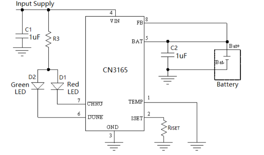
Here we need a resistor to set the maximum output battery charging current, A capacitor on battery terminal for power supply noise cancellation. And a few led indicators for battery changing and done mode. In single cell operation the feedback pin is directly connected to the battery terminal and continuously monitors the battery voltage for automatic charging restart and power down. The same charging IC can be used to charge more than 1 battery @1Amp maximum by feeding the feedback pin with voltage dividers.
Modified Circuit:
I modified the circuit to add some external protection features. I have added a USB type C input, a TVS diode to reject any spike in solar output and a forward bias diode to make it polarity friendly, which can be seen in the schematics.
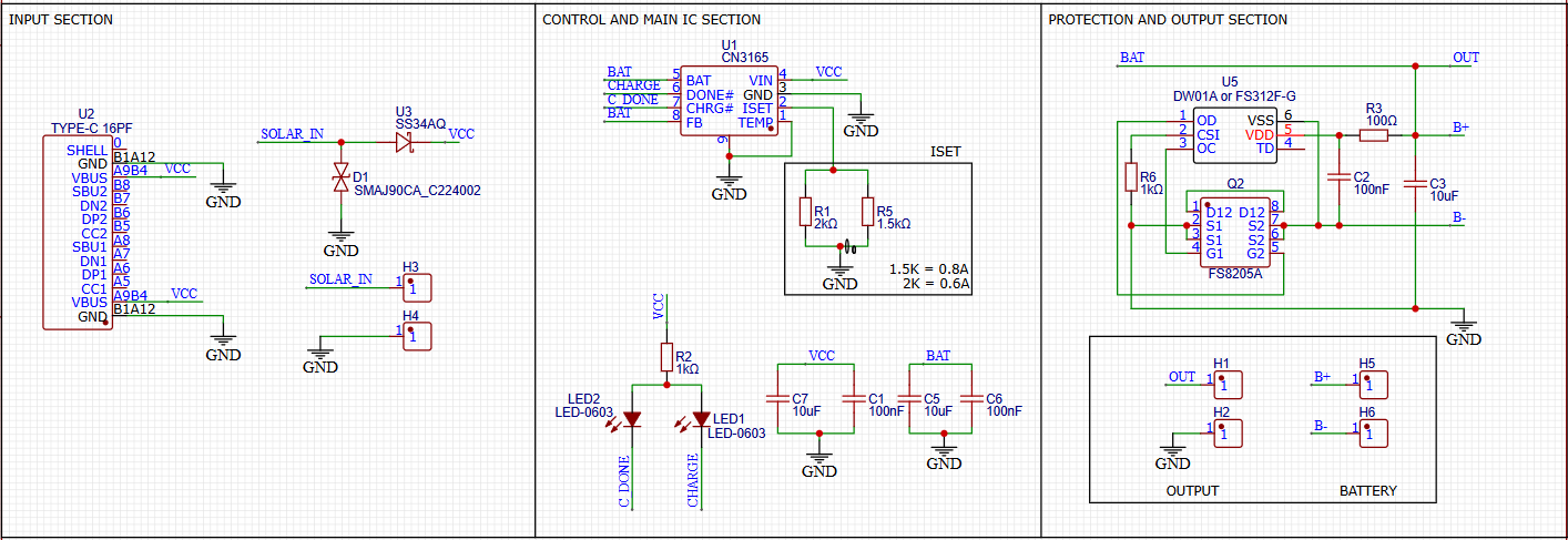
In section 2, IC is placed itself with 2 resistors to set the current, led indicators and some coupling capacitors for the IC.
In section 3, output is taken from a pin header, And it also contains the same protection circuit which is there on TP4056. All this packed into a small form factor.
PCB Layout:
This is the Hardware...
Read more »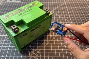
 Sagar 001