 imanolink
After calculating and listing the dimensions of the different parts that would serve as axes for our various gears, we cut them out with the laser cutter. We also 3D-printed a cylinder, which would also serve as an axis, since it is not a shape that can be made with the laser cutter.
We realized that the cut-out shapes would not make good axes for the gears that are not directly connected to the motor because they would need to have a circular shape. So, we rounded and widened the holes in the gears using a drill. Then we modeled new cylinders on Fusion with the same dimensions, but this time, we added bases to be able to fix the axes to the dial.
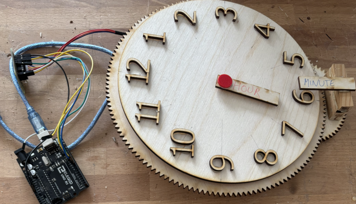
We also used the laser cutter to make the numbers for the clock. We took the opportunity to remake the dial and the hands, which were lacking a hole to pass the axes through. We then glued the numbers to the dial with a hot glue gun. After that, we used it to start assembling our clock, gluing some of the gears.
We finished the 3D printing of the cylinders with bases, then we assembled them with the rest of the structure by sanding the parts that needed resizing. We then finished the assembly of the clock by fitting all the gears as best as we could. We faced some difficulties because the clock dial obstructed our view and our movements, but we still managed to handle it. We also added pieces around the dial: a shim to keep the dial in the air at a fixed position so it wouldn't block the movement of the gears, and the support for the minute hand, which we had to elevate to allow it to pass over the dial.
We also changed the code and the wiring for the step motor so that it properly rotates our central gear and thus the minute hand at a speed of 1 turn per hour.
Finaly, a big part of the project was done with this session.
Discussions
Become a Hackaday.io Member
Create an account to leave a comment. Already have an account? Log In.