Close
0%
0%

PowerPulse Inverter

The PowerPulse Inverter converts 12V DC to AC voltage using square wave pulses, offering modular design for easy troubleshooting and upgrade

Similar projects worth following
0 followers
Greetings everyone, and welcome back.
This is the PowerPulse Inverter project, a simple and effective way to convert 12V battery power into a stable AC voltage.
This unique inverter design utilizes the CD4047 IC to generate precise square wave pulses with powerful MOSFETs and a 12-0-12V transformer to achieve an adequate AC output.
The PowerPulse Inverter enhances heat management, troubleshooting, and updates by separating the circuit into two primary sections for modularity: the CD4047 Driver Circuit and the Mosfet Board.

PCB DESIGN PROCESS

We begin this project by designing the PCB, which consists of two primary sections for modularity.

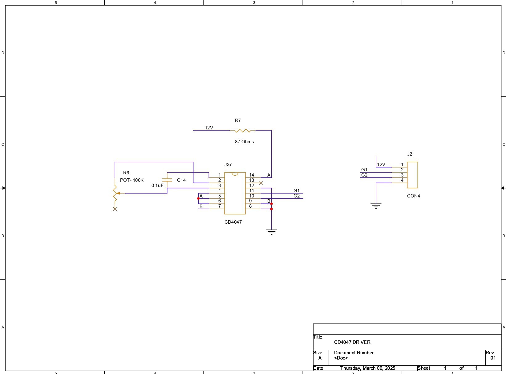
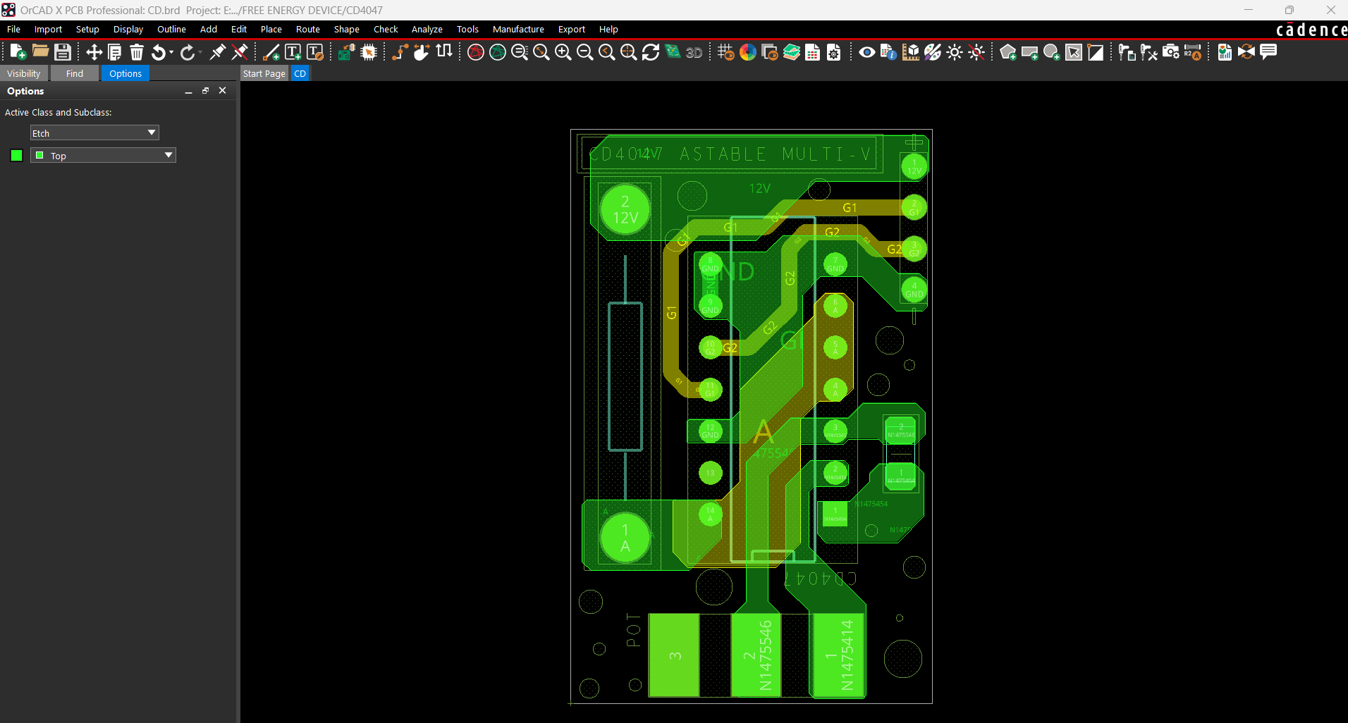
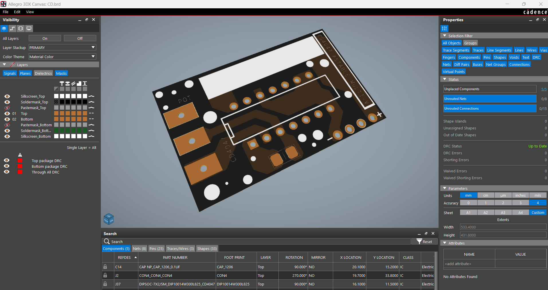
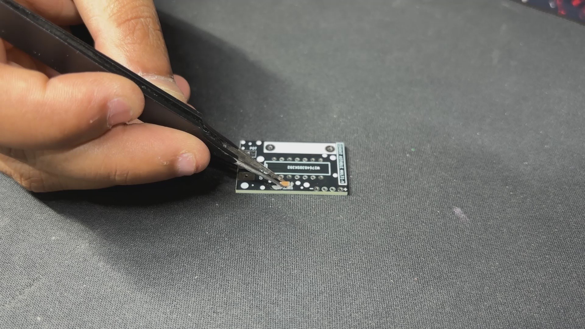
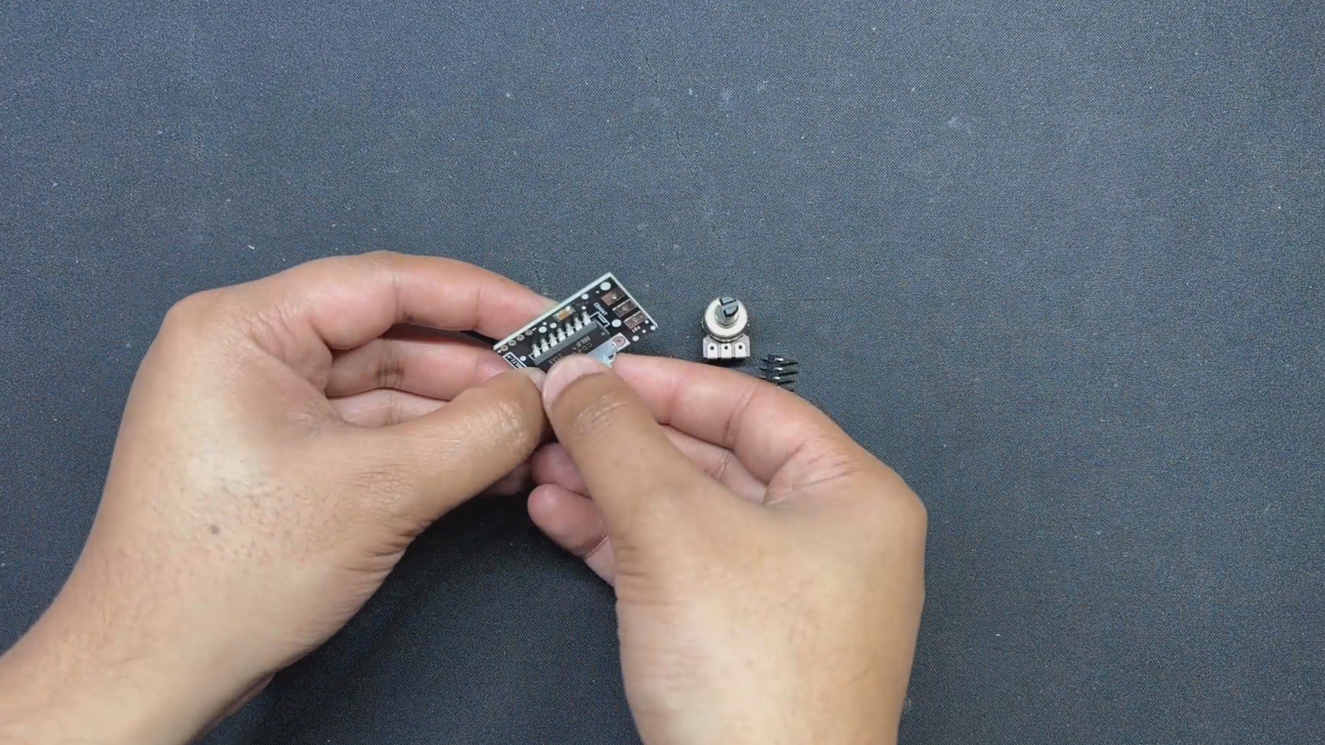
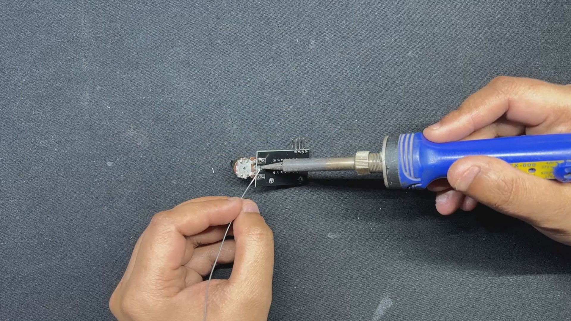
The CD4047 Driver is the initial section, which consists of the CD4047 IC, a potentiometer, and a load resistor. The CD4047 IC generates square wave pulses, and the frequency can be adjusted using the potentiometer. This provides fine control over the output frequency, which is generally set to 50 Hz or 60 Hz for normal AC applications. The load resistor ensures that the CD4047 IC's output pulses remain stable.

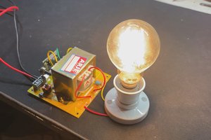
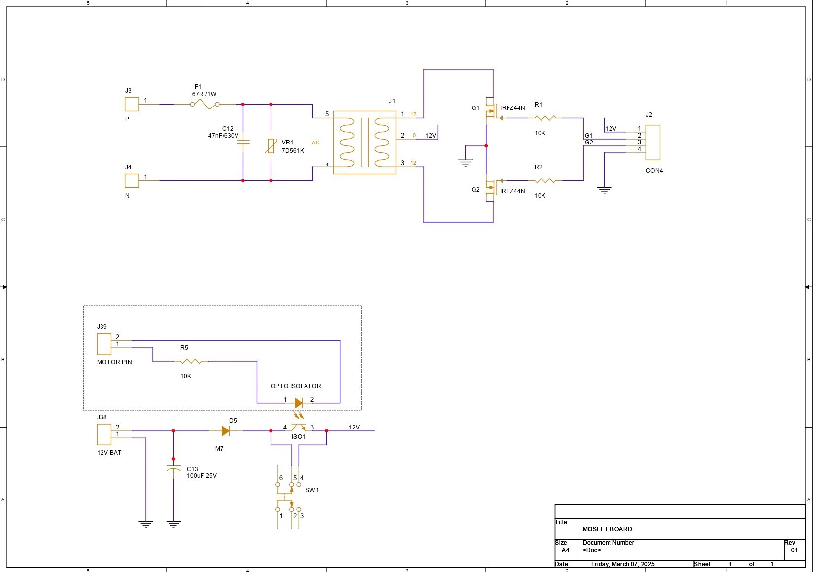
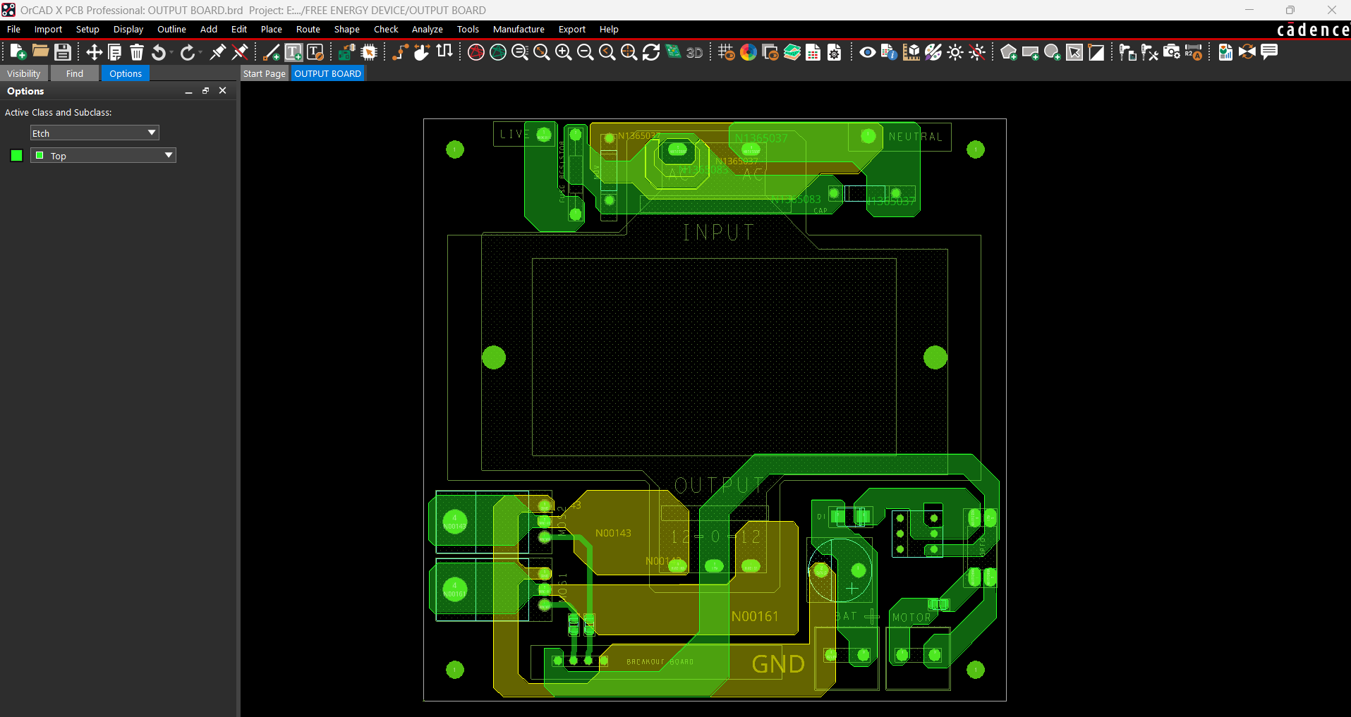
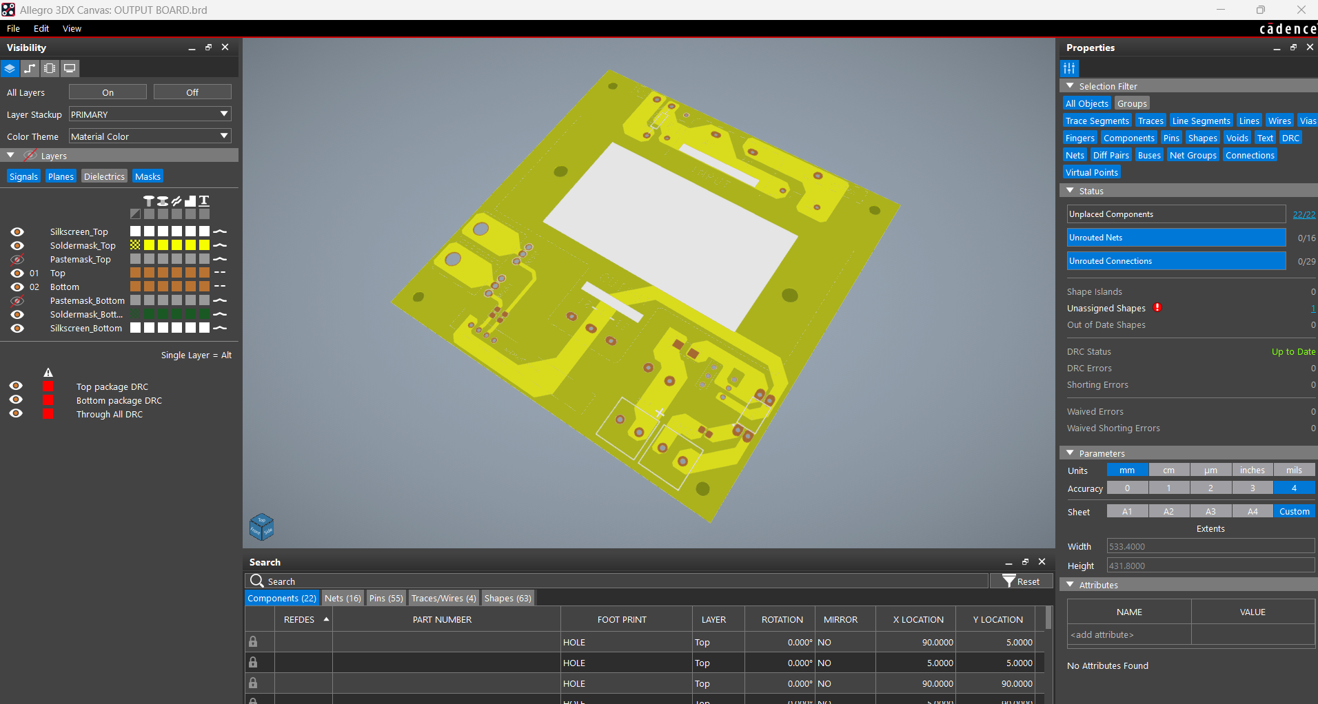
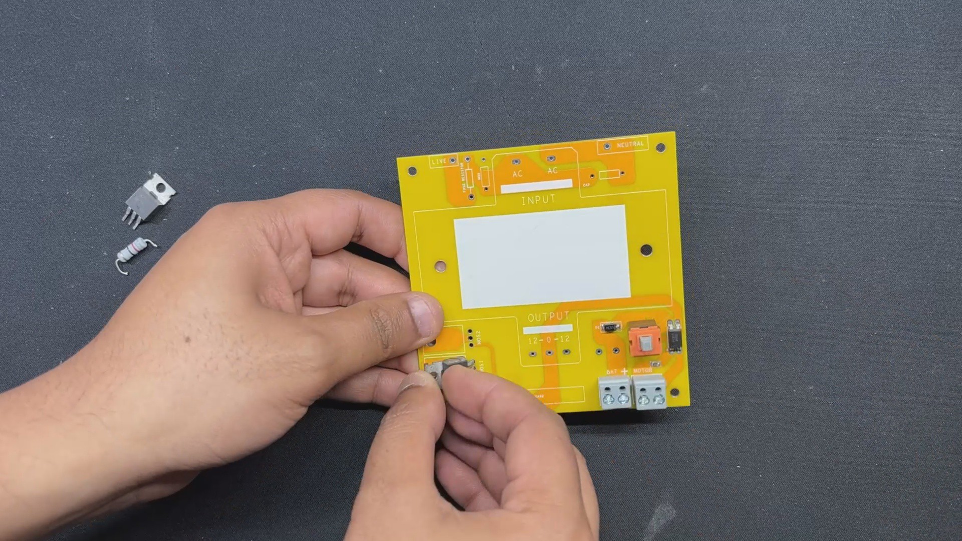
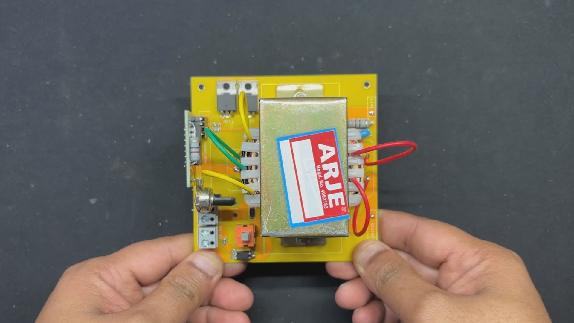
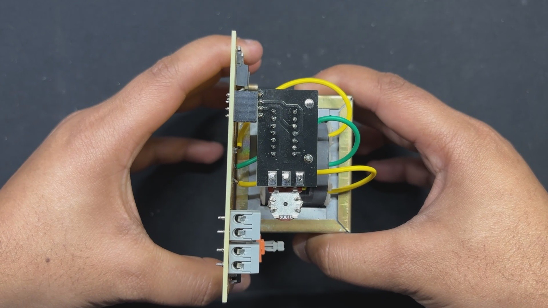
These pulses are then sent into the circuit's second section, the MOSFET BOARD, which includes MOSFETs, a transformer, capacitors, and other essential components.

The MOSFETs amplify the square wave pulses received from the CD driver by turning on and off, enhancing the signal. The amplified signal is then fed into the transformer's primary winding, which increases the voltage to the necessary AC level.

The transformer turns the amplified square wave signal into a higher-voltage AC output. Capacitors are employed to filter the output, resulting in a smooth AC waveform with little noise and ripples. This arrangement simplifies troubleshooting and upgrading while also improving heat management by dispersing components across multiple boards. As a result, the inverter efficiently transforms 12V DC power into a uniform AC voltage, making it suited for a variety of applications that require AC power from a DC source.

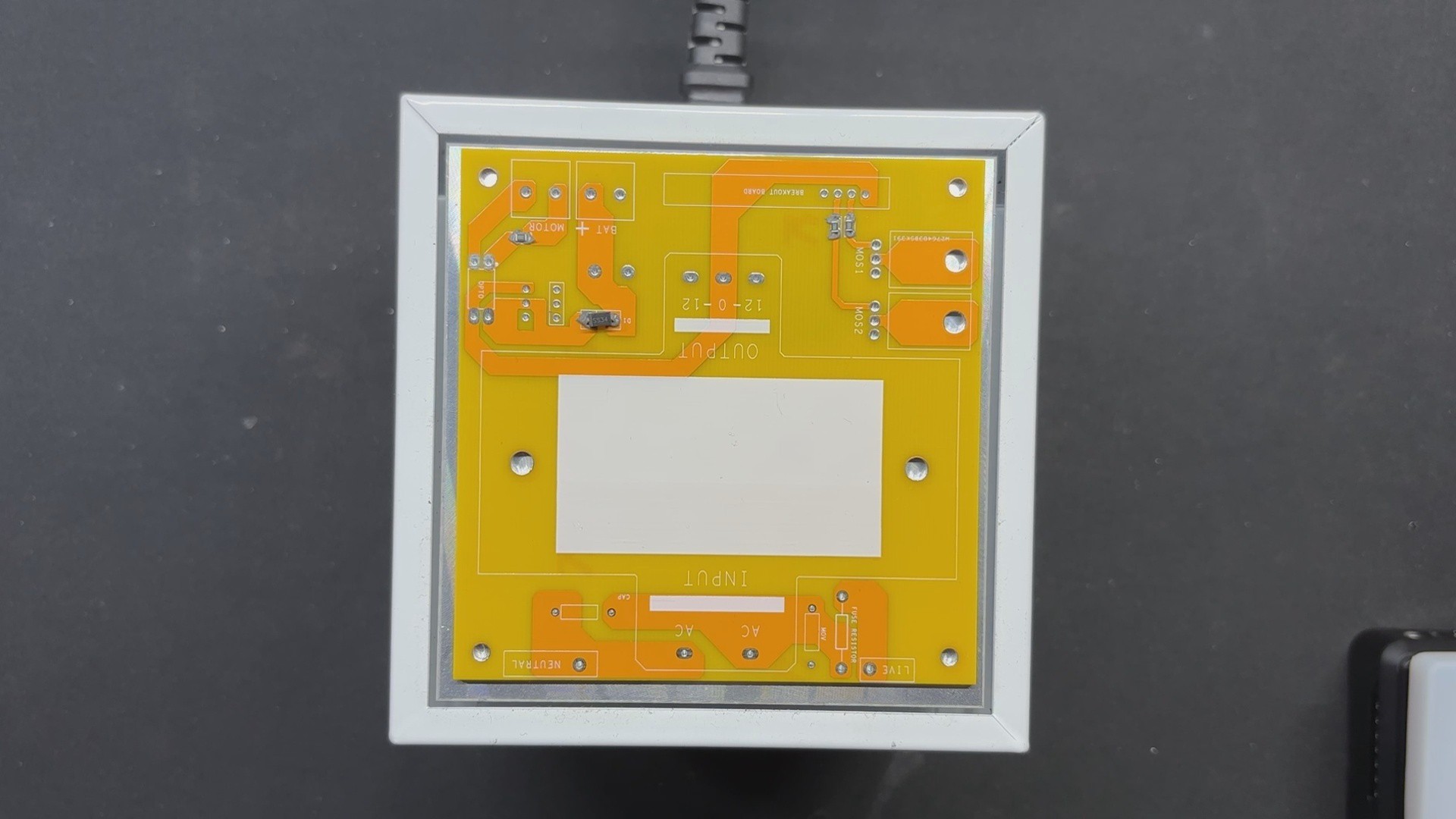
This board also has two mounting holes, so the transformer can be securely attached with nuts and bolts to the circuit.

We've also added CON 2 screw terminals, via which we'll connect a 12V lithium battery pack to the circuit.

PCBWAY Service

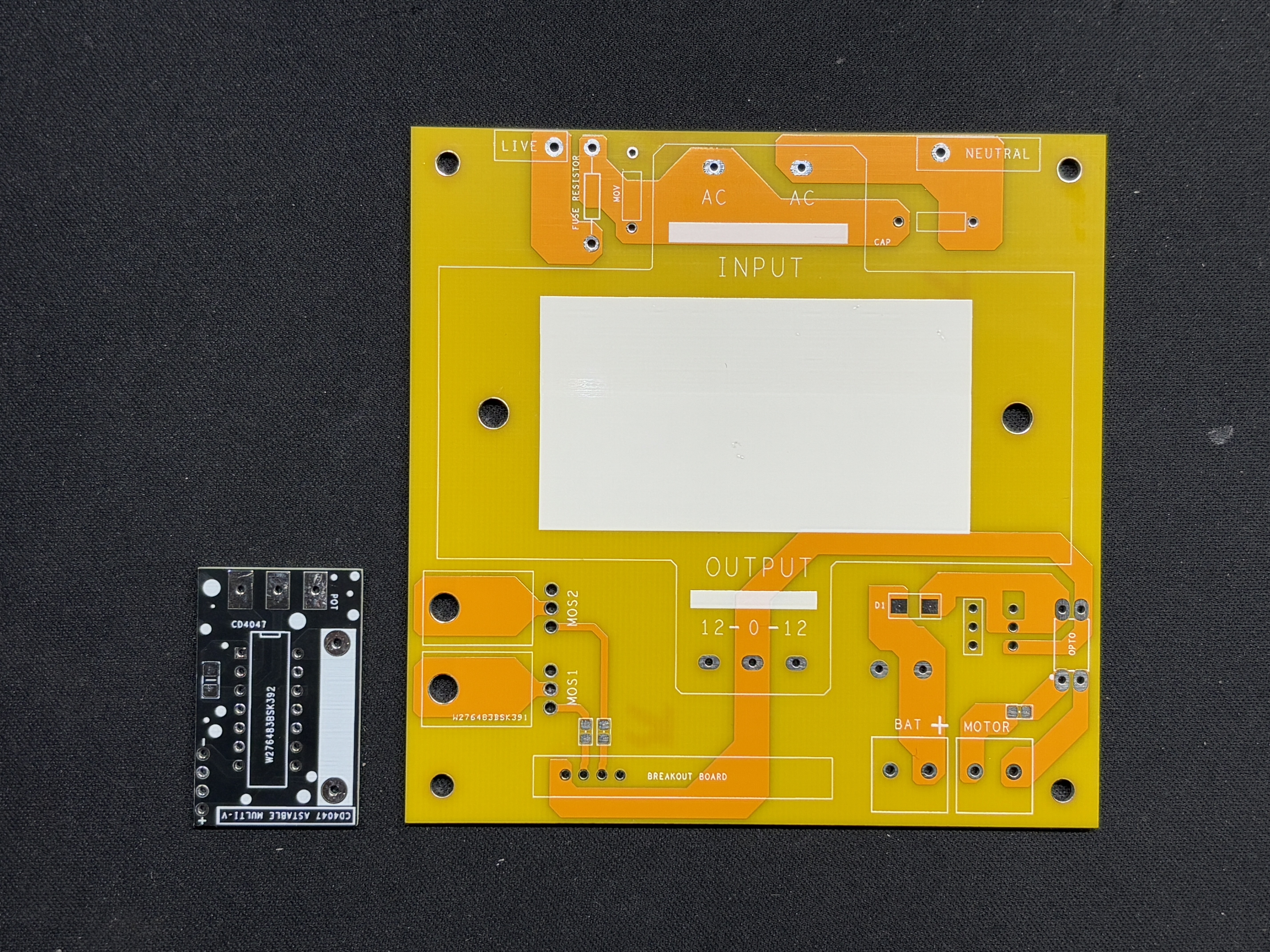
We created two PCBs for this project: the CD4047 driver and the MOSFET board. Two orders were placed, one for the CD4047 driver and one for the MOSFET board.

The CD4047 Driver Board was ordered with black solder mask and white silkscreen, and the MOSFET Board was ordered with yellow solder mask and white silkscreen.

After placing the order, the PCBs were received within a week, and the PCB quality was pretty great.

Their commitment to quality and customer satisfaction has been unwavering, leading to significant growth and expansion.

Also, PCBWAY is organizing a PCB badge-making competition to mark their 11th anniversary, inviting designers and makers to showcase their creativity by designing badges that celebrate the company's legacy and envision a bold future. Participants must incorporate the elements "PCBWay" and the number "11" in their designs and can use PCB, PCB+SMT/THT, or PCB+3D printing techniques. Submissions can be posted in the comments, emailed, or shared on social media with the hashtag #PCBWay11BadgeContest.

Prizes include cash, PCBway coupons, and free prototyping services for all qualifying entries.

You guys can check out PCBWAY if you want great PCB service at an affordable rate.

  • 1
    MOSFET BOARD ASSEMBLY
    • We begin the Mosfet board assembly procedure by applying solderpaste to each SMD component pad with a solder paste dispenser needle; the solderpaste we use is Sn/PB 63/37.
    • Next, we use an EDS tweezer to select and position all of the SMD components.
    • We lifted the PCB and placed it on the SMD Reflow hotplate, which heated it from below until it reached the solder paste melting temperature. As soon as the PCB reaches the solder paste melting temperature, the solder paste melts and all components are attached to their pads.
    • After soldering all of the SMD components, we begin the THT assembly process, which begins with the installation of all through-hole components such as MOSFETs, resistors, CON4 connectors for driver board placement, CON 2 screw terminals, switch, and so on.
    • We next fip the board and solder all of the THT component pads with a soldering iron.
    • After we've added all of the through-hole components, we'll add the transformer to complete our board.
    • The transformer is first installed, and then two M2.5 nuts and bolts are used to fasten it to the mounting holes on the PCB.
    • We next connected the transformer's AC wires to the AC side of the circuit, followed by the DC wires.

    The Mosfet -Transformer Board has been completely assembled.

  • 2
    CD4047 DRIVER BOARD
    • The CD4047 Driver Assembly process begins by applying solderpaste to the SMD capacitor pad. Our driver board includes one SMD component, the 100 nF decoupling capacitor.
    • We used a tweezer to pick up and place the SMD capacitor on its pad.
    • We used our tiny reflow hotplate from PCBWAY giftshop to solder the capacitor onto the PCB by heating the solder paste to its melting point.
    • The through-hole components, which comprise the CD4047 IC itself, an 82 Ohm load resistor, a potentiometer, and a CON4 header pin connector, are all added in their place and then soldered from the bottom side of the PCB using a soldering iron.
  • 3
    CD4047 & MOSFET BOARD Assembly
    • Following assembly verification of both the Mosfet board and the CD4047 driver circuit, we pick the CD4047 driver circuit and connect it to the Mosfet board via both boards' con4 ports.
    • We have attached a female header pin to the Mosfet board and a male header pin to the CD4047 board. Using these two connectors, we can join them together as if they were modules.
    • Because of this connector, we can later modify or switch the CD4047 for a microcontroller or a better circuit to improve the setup.

View all 8 instructions

Enjoy this project?

Share

Discussions

Similar Projects

Does this project spark your interest?

Become a member to follow this project and never miss any updates