 Stepan Skopivskiy
For one year, I forgot about Homelink and just used the car until my colleague bought an A4 2018 MY and started searching for a solution to the same problem. And here's where the new story begins.
We started by sharing what we had learned about Homelink. The amount of information was not large and helpful. With his car, we tried to do the same manipulation - coding and adaptation- but it did not help either.
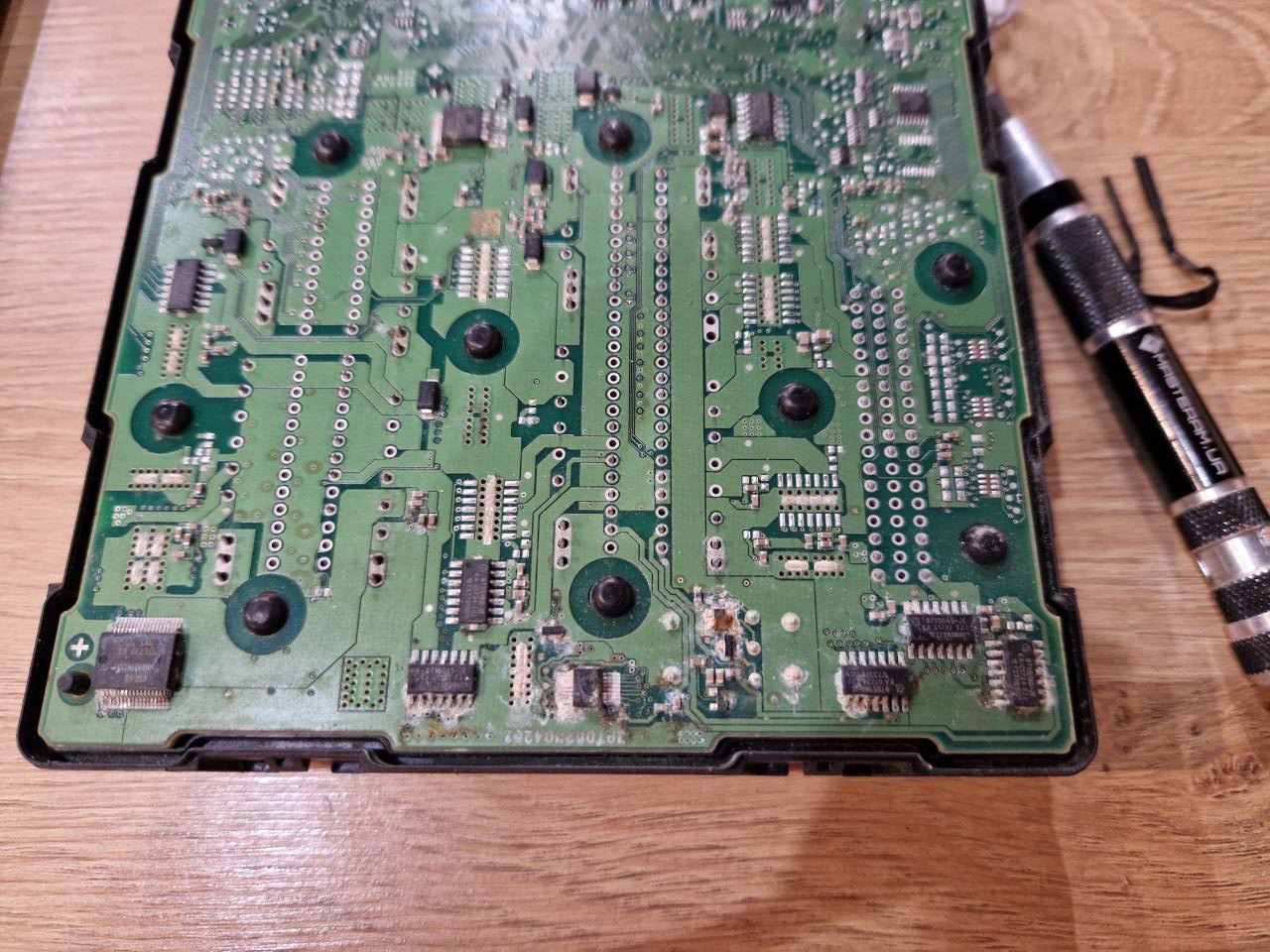
We were able to change the coding, but the adaptations were secured with the security access login. After that, the idea comes. The HomeLink module is connected by the LIN bus. So, it should be pretty "stupid". It should do simple operations and not more. How wrong I was...
The first idea was to test all the things right on my car. But it is totally useless because it requires running between the apartment and the parking a lot times. Also, I did not find a way to connect to the LIN bus in the car. All places are covered by trims. And that LIN bus is present only in a few places without any connectors on its way.
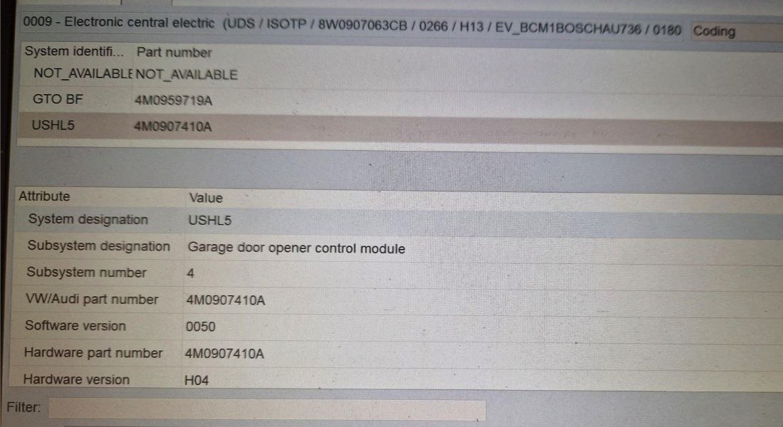
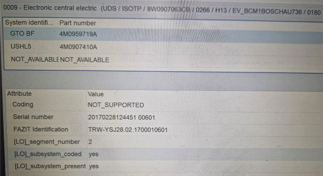
I found and ordered the first two components of the HomeLink system - HomeLink physical buttons (4M0959719A) and the HomeLink module (4M0907410A). In parallel, I started to search for information on how the LIN bus works and information regarding the communication protocols. But during the investigation, I also found that the LIN bus requires the master, which is driving the bus. The details can be found here: https://www.csselectronics.com/pages/lin-bus-protocol-intro-basics.
So, I also ordered the BCM (Body control module) (8W0907063CB). As I need it just for the experiments, I was searching for the cheapest one.
The seller sent another one instead. And I start the experiments.
BCM has 3 connectors:
- -T54c- (A)
- KL31 (permanent negative)
- pin 11
- KL31 (permanent negative)
- -T73a- (B)
- KL30 (permanent positive)
- pin 2
- pin 12
- pin 66
- pin 73
- KL31 (permanent negative)
- pin 40
- pin 63
- KL15 (ignition)
- pin 7
- pin 19
- LIN bus
- pin 24
- KL30 (permanent positive)
- -T73b- (C)
- KL30 (permanent positive)
- pin 1
- pin 12
- pin 66
- pin 73
- KL31 (permanent negative)
- pin 63
- CAN bus
- pin 40
- pin 41
The complete preparation for the setup looked next. The OBD2 was not connected yet because of a lack of the correct connector for BCM.
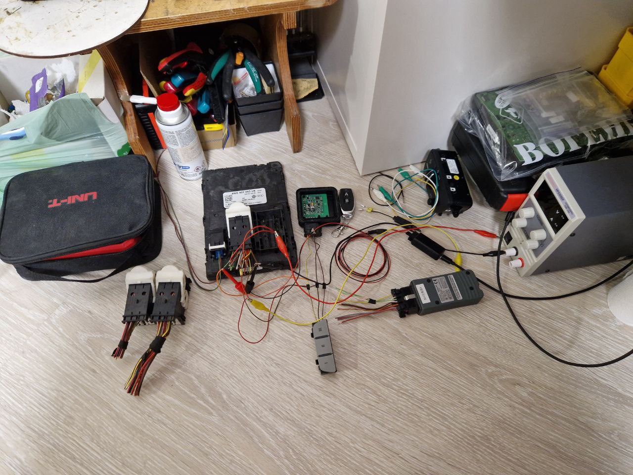
After connecting all the pins (including the ignition one) and powering on the BCM from the laboratory power supply, nothing interesting happened. The buttons were not reacting on clicks. I connected the diagnostic device to the BCM CAN bus directly, and the ODIS recognized and even reported the clicks. The LIN bus got activity, too.
As the LIN bus had activity, I did some capturing of the LIN. The Logic2 capture with hold buttons for the while is in the attached file. The logic analyzer was a cheap clone of the Logic2 devices from AliExpress.
Besides that, the buttons were still not reacting to clicks.
Discussions
Become a Hackaday.io Member
Create an account to leave a comment. Already have an account? Log In.