 TJ
TJProject Ideation:
I was changing out the stock pickups in my guitar to a single humbucker and I've had the idea of putting an effects circuit in my guitar for some time now. My original idea was some sort of DSP circuit. However, after some initial designs, I realized that it deserved to be its own pedal. So I went with something simpler, a distortion circuit.
Block Diagram:
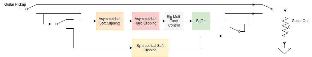
The block diagram shows the path(s) that the signal can take. The middle path is the main effect chain. The switching is accomplished with SPDT push-pull potentiometers.
Simulations:
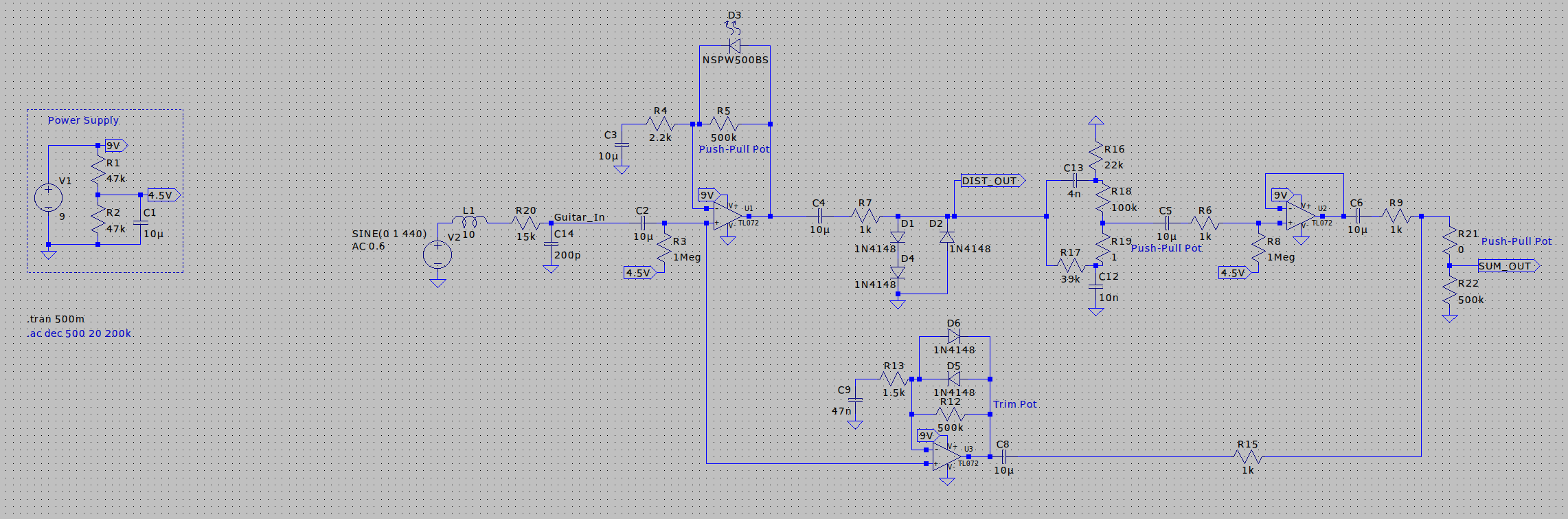
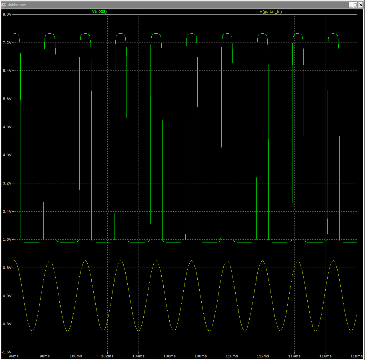
Before laying out the schematic and PCB in KiCad, I simulated the circuit in LTSpice and played with the values of the feedback resistors and the tone pot. 440Hz was the test frequency and I used a model of a humbucking pickup. The model was taken from Electronics for Guitarists by Denton J. Dailey. Below are some wave-forms from the simulation.
Gain(s) set to 0 and Tone set to 50/50:

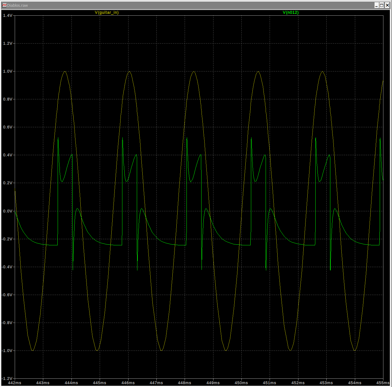
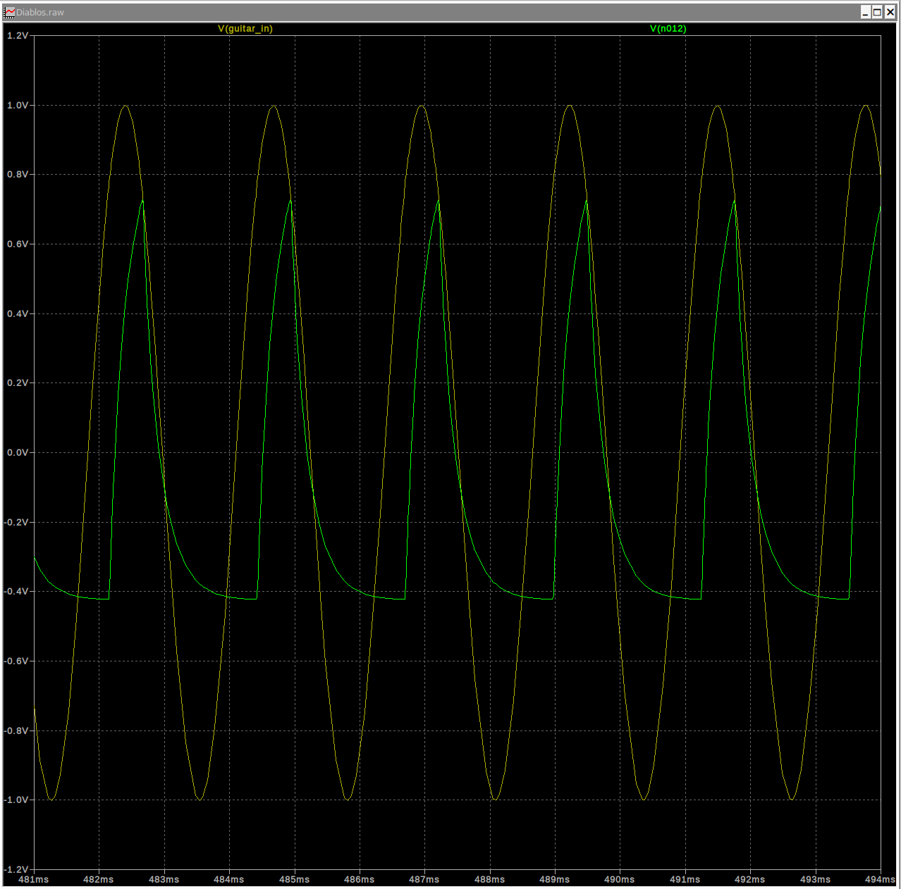
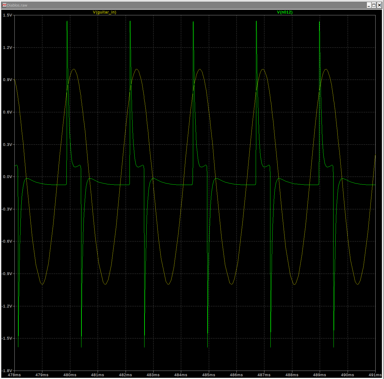
Asymmetrical Soft Clipping Stage with FB at 500k:
Asymmetrical Hard Clipping Stage with FB at 500k:
Distortion Maxed & Tone 50/50:
Distortion Maxed & Tone Low Pass:
Distortion Maxed & Tone High Pass:
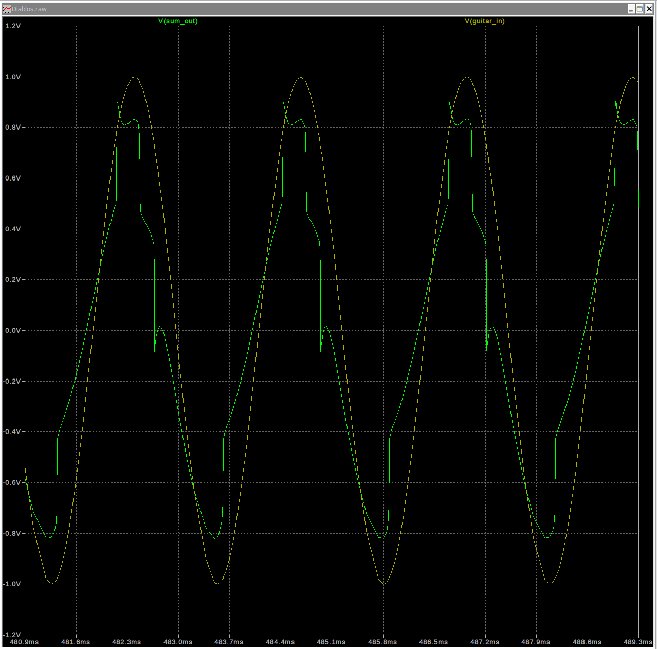
Parallel Symmetric Soft Clipping Maxed:

Distortion & OD Maxed & Tone 50/50:
Distortion & OD Maxed & Tone Low Pass:

Distortion & OD Maxed & Tone High Pass:

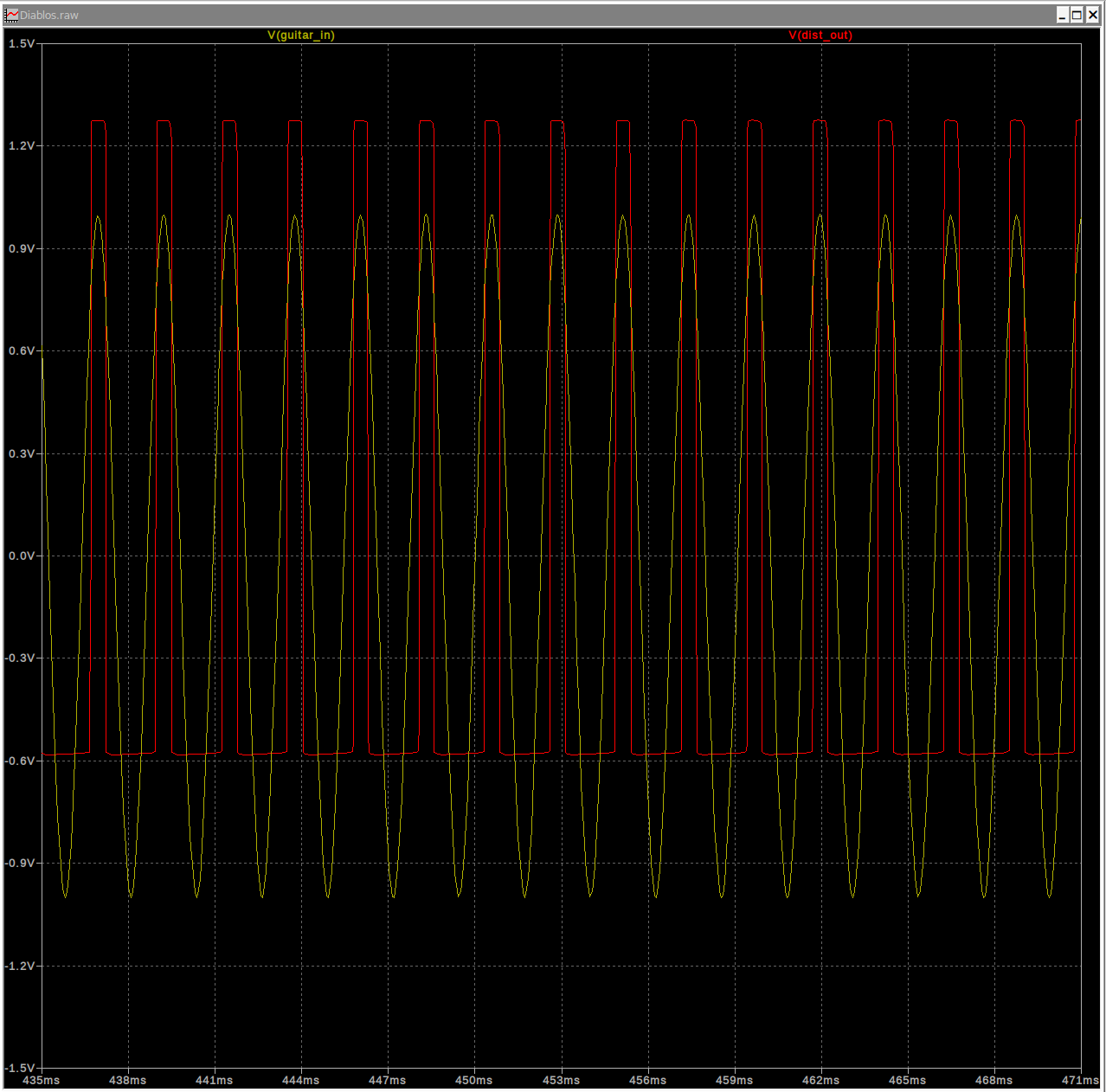
Schematic & PCB layout:
At this point, I was happy with the results of the simulation. I went about with the schematic and PCB layout in KiCad. The board outline was made by making a paper trace of the control cavity/pick guard of my guitar and subtracting a few millimeters. Then I scanned that outline, converted it to an SVG, and imported it as an edge cut in KiCad.

Since this is a personal project and won't be for sale, I used Diablos from FFXII: Revenant Wings as some silkscreen art. Once I was happy with the PCB layout, it was time to get the boards made. I went with JLCPCB for this project since I haven't used them for PCB/PCBA before. They assembled the boards with all of the SMD components. The THT parts, I would assemble myself since I have them on hand.
PCBs Arrive & Assembly:
The PCBs arrived quickly and I got to work finishing the assembly. The most tedious/fiddly part was wiring up all of the push-pull potentiometers. If I design a V2 of this board, I'll lay it out in a way that make the potentiometers easier to wire up.
Testing and Final Thoughts:
Before plugging my guitar into an amp, I tested the functionality of circuit using an oscilloscope to make sure that it behaved as I was expecting. It worked first try and I was happy. Once I saw it was working, I plugged my guitar into into my amp noodled around for a bit. Without knowing how it would sound, I was pleasantly surprised at the range of distortion that the circuit could produce. Overall, I had fun with this project and would encourage others to try something similar.