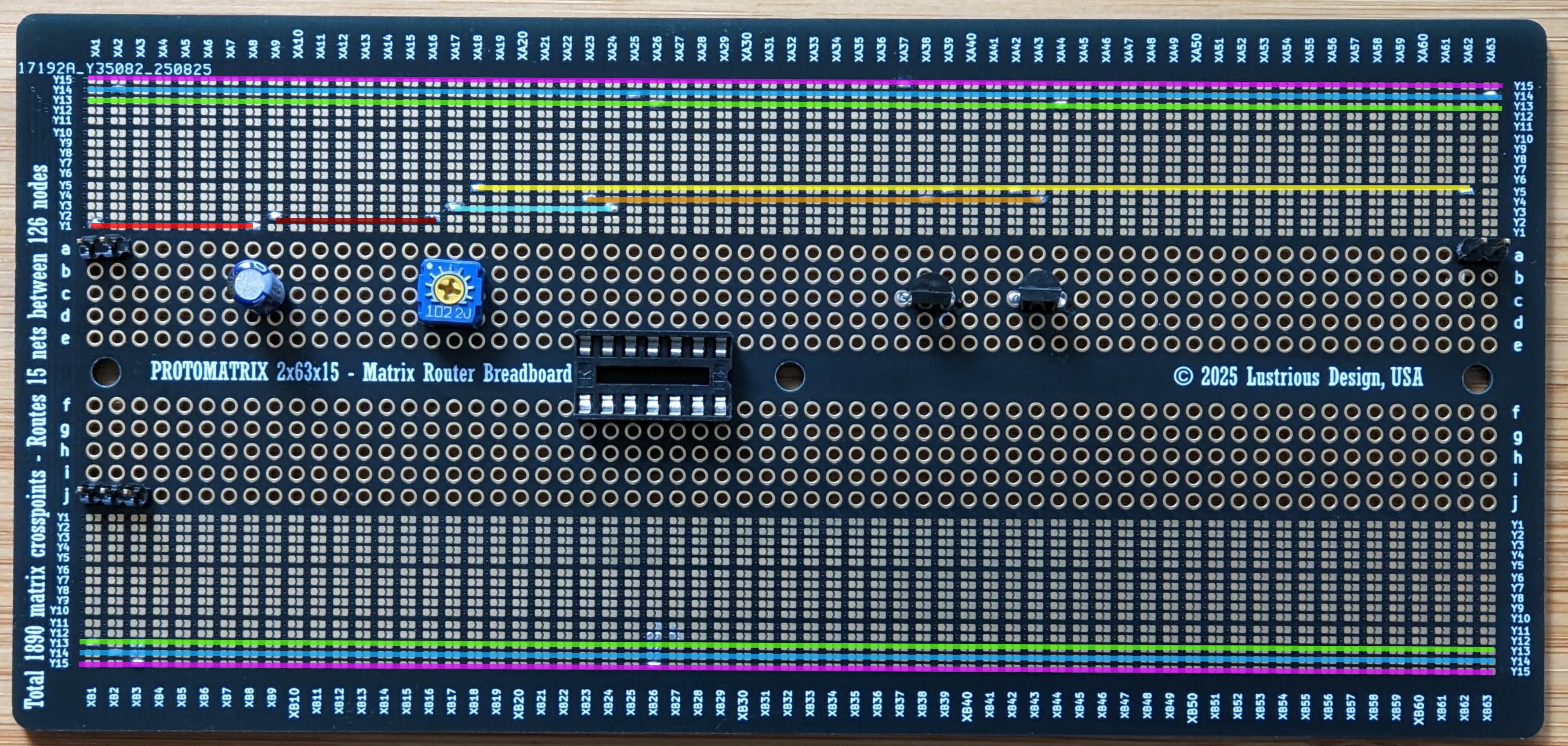
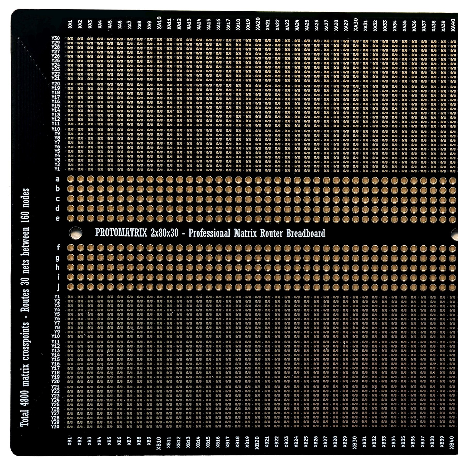
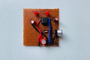
First breadboard with a matrix router
To make the experience fit your profile, pick a username and tell us what interests you.
We found and based on your interests.
I beefed up the amplifier I built couple months ago for this article. I was not satisfied with the tiny sound so I bough a PNP/NPN pair BD679/BD680, high-voltage op-amp LF412CN/NOPB, and a nice jack from Sparkfan. Results you can see... and hear!
The extra op-amp is for mixing left and right channels.
I had to bypass one high-current track with a wire instead of using the matrix (not visible, not the black wire), but the rest worked. Also, by-pass capacitors are absolute MUST when so much inductance is present in the tracks.
Engine sounds from THOR
In the previous log I made a sound amplifier that can be used to play a sound onto a speaker from line out of a controller or a similar device. Since the Halloween is approaching you could use it play some creepy sounds. Let say you have a crypt where you hear a scream of a tortured soul every minute. This is well-modeled by an exponential distribution with PDF (Probability Density Function):
Integrating this PDF from 0 to a, gives CDF (Cumulative Distribution Function):
The meaning of it is "what is the probability that I will wait a minutes for event to happen". In our case, what is probability that you will hear a scream after a minutes of not hearing anybody scream in the crypt.
Now, how do you turn that into a program?
The process is as follows, first you generate a uniformly distributed number U:
U = random.random()
Equate that to the CDF and solve for a
The intuition here is that we are sampling CDF using a uniform distribution, and converting from probability value to wait time by solving for a.
Here a is just a wait time in seconds (units don't matter) between playing sounds of different tortured souls. Python implementation using pygame for playing sounds shows below how to create a dismal atmosphere using sounds from Dark Messiah Of Might and Magic.
import pygame
import time
import random
import math
import os
pygame.mixer.init()
pygame.mixer.music.load("crypt_main_01.wav")
pygame.mixer.music.play(-1)
sound_fx = os.listdir("sounds")
random.seed(18512158625243168)
lmda = 1/60 # average rate of sound effects
while pygame.mixer.music.get_busy():
dt = -(1/lmda)*math.log(1-random.random())
pygame.mixer.Sound(os.path.join("sounds", random.choice(sound_fx))).play()
print("Sleeping for", dt, "seconds\n")
time.sleep(dt)
The result of that is that the sound effects are playing "at random", but on average they are spaced exactly 1 minute apart (lmda=1/60).
Playing sound effect talios_underground_drip_01.wav
Sleeping for 128.69566205426352 seconds
Playing sound effect womb_pit-spiders2.wav
Sleeping for 77.31571960719558 seconds
Playing sound effect crypt_main_01-voice02.wav
Sleeping for 118.22675017236637 seconds
Playing sound effect a_windgust03.wav
Sleeping for 9.406140801162172 seconds
Playing sound effect talios_underground_drip_05.wav
Sleeping for 143.527373362454 seconds
Playing sound effect karthal_city_interior_rndc_03.wav
Sleeping for 233.31308460867473 seconds
Playing sound effect boat_inside_rndb_03.wav
Sleeping for 34.25852255619906 seconds
Playing sound effect menelag_inside-violins05.wav
Sleeping for 45.78918863544417 seconds
Playing sound effect stonehelm_paokai_int_wind_02.wav
Sleeping for 26.795201242341257 seconds
Playing sound effect kharthal_roofs-thunder03.wav
Sleeping for 40.608196333385564 seconds
Playing sound effect boat_inside-creak01.wav
Sleeping for 79.57805612346229 seconds
Playing sound effect karthal_city_cellar_rndc_03.wav
Sleeping for 7.086597576435293 seconds
Playing sound effect stonehelm_paokai_ext_wind_02.wav
Sleeping for 74.11938743159087 seconds
Playing sound effect goblin_main-bat03.wav
Sleeping for 19.494657143535072 seconds
Playing sound effect talios_inside_no_wind.wav
Sleeping for 56.11492592704442 seconds
Playing sound effect talios_inside-creaks01.wav
Sleeping for 65.92188091086814 seconds
Playing sound effect orc_caves_02_creak_04.wav
Sleeping for 114.70192969525529 seconds
Playing sound effect kharthal_roofs-thunder03.wav
Sleeping for 53.66492417273082 seconds
Playing sound effect womb_03_3.wav
Sleeping for 1.850743553746255 seconds
Playing sound effect crypt_catacombs.wav
Sleeping for 46.001320343673086 seconds
Playing sound effect karthal_city_interior_rndb_02.wav
Sleeping for 30.43711004687171 seconds
Playing sound effect upper_temple_main.wav
Sleeping for 6.600836081999313 seconds
Playing sound effect karthal_gates-bird0204.wav
Sleeping for 53.59866821050122 seconds
Playing sound effect crypt_goddess...
Read more »
In this log I'm going to use my matrix router breadboard to put together a simple audio amplifier made of push-pull stage and a op amp in inverting amplifier configuration. If you ever tried building a push-pull stage without feedback you probably noted horrible distortion around zero due to transistors falling out of active region and starting to act non-linearly.
Note the flat regions of the waveform where input is crossing 0.6V.
If you were to connect an actual speaker it would look even worse due to inductance and dynamic nature of the load.
The op amp has a closed-loop gain of 500/100 = 5. And in the circuit above it is simply providing a linear gain before power stage as well as low impedance. The fix is surprisingly simple, just close op amp feedback around the output and it will do its best to keep it linear! In the next circuit, the op amp will become aware of the push-pull stage.
The magic of an op amp is that it is kind of a control system in itself working in a closed loop with feedback. By closing its feedback loop around a parameter you want it to control you can improve your circuit performance. In this case this circuit closed the feedback loop at output of the push-pull stage so that the op amp can maintain a gain of 5 despite non-linear behavior of the transistors around zero. I read about this trick in the Art Of Electronics, and this is the circuit we are going to build using a matrix router.
NOTE: The capacitor polarity in this circuit does not matter. This sometimes bothers people, they think they are hurting the poor thing. The purpose of capacitor is to block DC bias. If there's DC voltage across the capacitor you should orient it according to polarity. You may ask: but doesn't audio signal change polarity when zero-crossing? Yes, but for AC of large enough frequency the capacitor is considered to be a short circuit. Therefore the voltage drop across the capacitor for AC signal is zero and polarity does not matter. Bottom line, watch DC bias, don't worry about AC. If you got it wrong, it will explode and you will know you got it wrong. In my circuit I oriented negative side to the virtual ground node, because at DC inverting input of the op amp will try to be equal to whatever is connected to the non-inverting input (ground). So if there was a DC bias coming from some audio input, it would be on the positive side of capacitor.
Since I'm going to use a matrix router breadboard, the first thing to do is to split the circuit into NETs. A NET is a just a group of connected pins. This is no different from the process that a PCB layout software or a circuit simulator would do, except we have to do it by hand. Below I colored and labeled all NETs.
There's really no magic to it, you just put them anywhere you want, that's kind of the point of using a matrix router.
The next step is to close the jumpers. I go over each net's Y row and close the jumpers at X columns where the device pin is located. It is best to do it one Y row at a time to make sure you don't miss anything.
I also added connectors for power, audio input and audio output for external speaker and for probing. I usually use outer tracks Y15, Y14, Y13 for power distribution, similar to conventional breadboard (obviously conventional breadboard does not have a dual power supply rail, but here you can do whatever you want). The op amp that I used was LM324N (though mine had issues and I rewired it for LM412). I also replaced the resistors with a 1k potentiometer. Transistors are N23904 and N23906, they do the job, but I would like to replace them with something heftier.
Below, I also colored sections of Y rows using same colors as in schematic. In hindsight, I should've had the board made in white so I could use a color marker to draw on it.
The matrix...
Read more »
Matrix routing is one of those concepts that everyone claims to understand—until they actually face the challenge of routing something with a matrix and end up in a tangled mess. I first encountered matrix routing when exploring PXI-based matrix switching systems. In that world, the prevailing mindset is to spend a hefty amount each year on the "magic" routing software and to avoid reinventing the wheel. But honestly, what's so wrong with reinventing your own wheel every now and then? That's one of the things I love most about engineering: understanding how things work so you can put your own spin on them, combine ideas, remix, and integrate them into something new.
Matrix routing, at its core, is actually quite simple. Here’s a step-by-step guide to implement any arbitrary circuit using a matrix:
It might take a little time to fully grasp why these steps work, but once you do, you'll have a powerful tool at your disposal.
I made some router boards to try the idea out. You can get them if you want to support my project: Protomatrix 2x30x80. More to come!
Create an account to leave a comment. Already have an account? Log In.
Yes, it's been a bear trying to explain in it, no one gets it :). Including once when I pitched a testing system based on a matrix. People do learn better by examples, myself including. I will post something that blinks a LED or something.
Haha yeah I hear that. Pretty sure I get it but it is quite a different way of thinking about circuit layouts.. like I can imagine a similar thing with all your components in a single line. Maybe solder joints on the underside too who knows
Become a member to follow this project and never miss any updates
Xtreme Tech
Dr. Cockroach
MaBe42
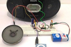
Have you got any simple examples of using this board? It's a little tricky to understand :)