 Vlad Shcherbakov
Designing The Circuit
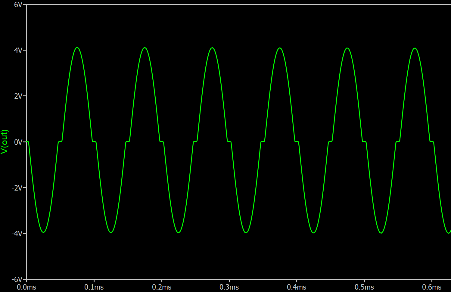
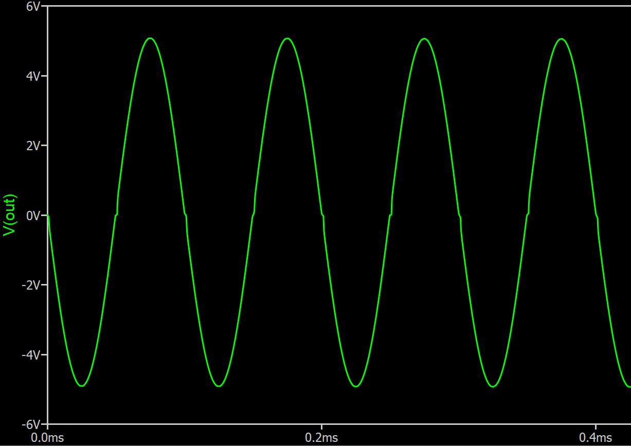
In this log I'm going to use my matrix router breadboard to put together a simple audio amplifier made of push-pull stage and a op amp in inverting amplifier configuration. If you ever tried building a push-pull stage without feedback you probably noted horrible distortion around zero due to transistors falling out of active region and starting to act non-linearly.
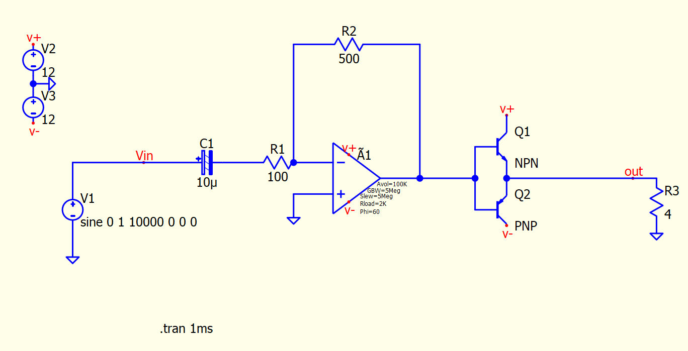
Note the flat regions of the waveform where input is crossing 0.6V.
If you were to connect an actual speaker it would look even worse due to inductance and dynamic nature of the load.
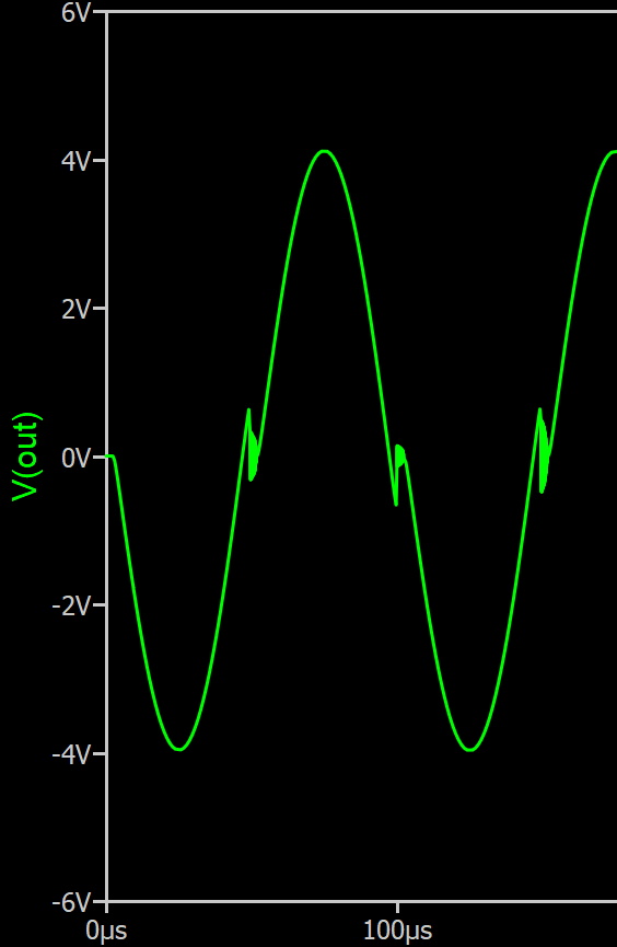
The op amp has a closed-loop gain of 500/100 = 5. And in the circuit above it is simply providing a linear gain before power stage as well as low impedance. The fix is surprisingly simple, just close op amp feedback around the output and it will do its best to keep it linear! In the next circuit, the op amp will become aware of the push-pull stage.
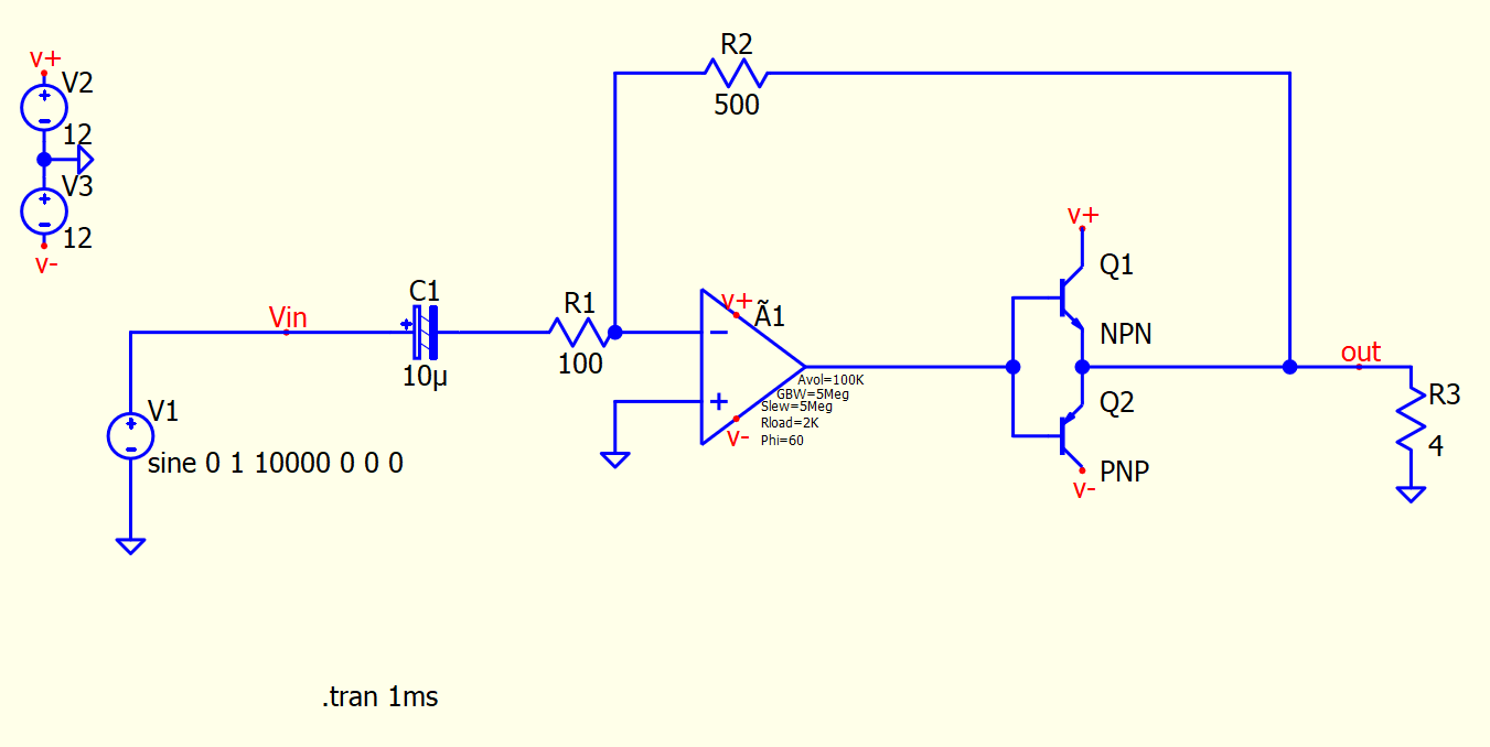
The magic of an op amp is that it is kind of a control system in itself working in a closed loop with feedback. By closing its feedback loop around a parameter you want it to control you can improve your circuit performance. In this case this circuit closed the feedback loop at output of the push-pull stage so that the op amp can maintain a gain of 5 despite non-linear behavior of the transistors around zero. I read about this trick in the Art Of Electronics, and this is the circuit we are going to build using a matrix router.
NOTE: The capacitor polarity in this circuit does not matter. This sometimes bothers people, they think they are hurting the poor thing. The purpose of capacitor is to block DC bias. If there's DC voltage across the capacitor you should orient it according to polarity. You may ask: but doesn't audio signal change polarity when zero-crossing? Yes, but for AC of large enough frequency the capacitor is considered to be a short circuit. Therefore the voltage drop across the capacitor for AC signal is zero and polarity does not matter. Bottom line, watch DC bias, don't worry about AC. If you got it wrong, it will explode and you will know you got it wrong. In my circuit I oriented negative side to the virtual ground node, because at DC inverting input of the op amp will try to be equal to whatever is connected to the non-inverting input (ground). So if there was a DC bias coming from some audio input, it would be on the positive side of capacitor.
Split The Circuit Into Nets
Since I'm going to use a matrix router breadboard, the first thing to do is to split the circuit into NETs. A NET is a just a group of connected pins. This is no different from the process that a PCB layout software or a circuit simulator would do, except we have to do it by hand. Below I colored and labeled all NETs.

Solder Parts Into Matrix Router Board
There's really no magic to it, you just put them anywhere you want, that's kind of the point of using a matrix router.
Implement The NETs
The next step is to close the jumpers. I go over each net's Y row and close the jumpers at X columns where the device pin is located. It is best to do it one Y row at a time to make sure you don't miss anything.

I also added connectors for power, audio input and audio output for external speaker and for probing. I usually use outer tracks Y15, Y14, Y13 for power distribution, similar to conventional breadboard (obviously conventional breadboard does not have a dual power supply rail, but here you can do whatever you want). The op amp that I used was LM324N (though mine had issues and I rewired it for LM412). I also replaced the resistors with a 1k potentiometer. Transistors are N23904 and N23906, they do the job, but I would like to replace them with something heftier.
Below, I also colored sections of Y rows using same colors as in schematic. In hindsight, I should've had the board made in white so I could use a color marker to draw on it.
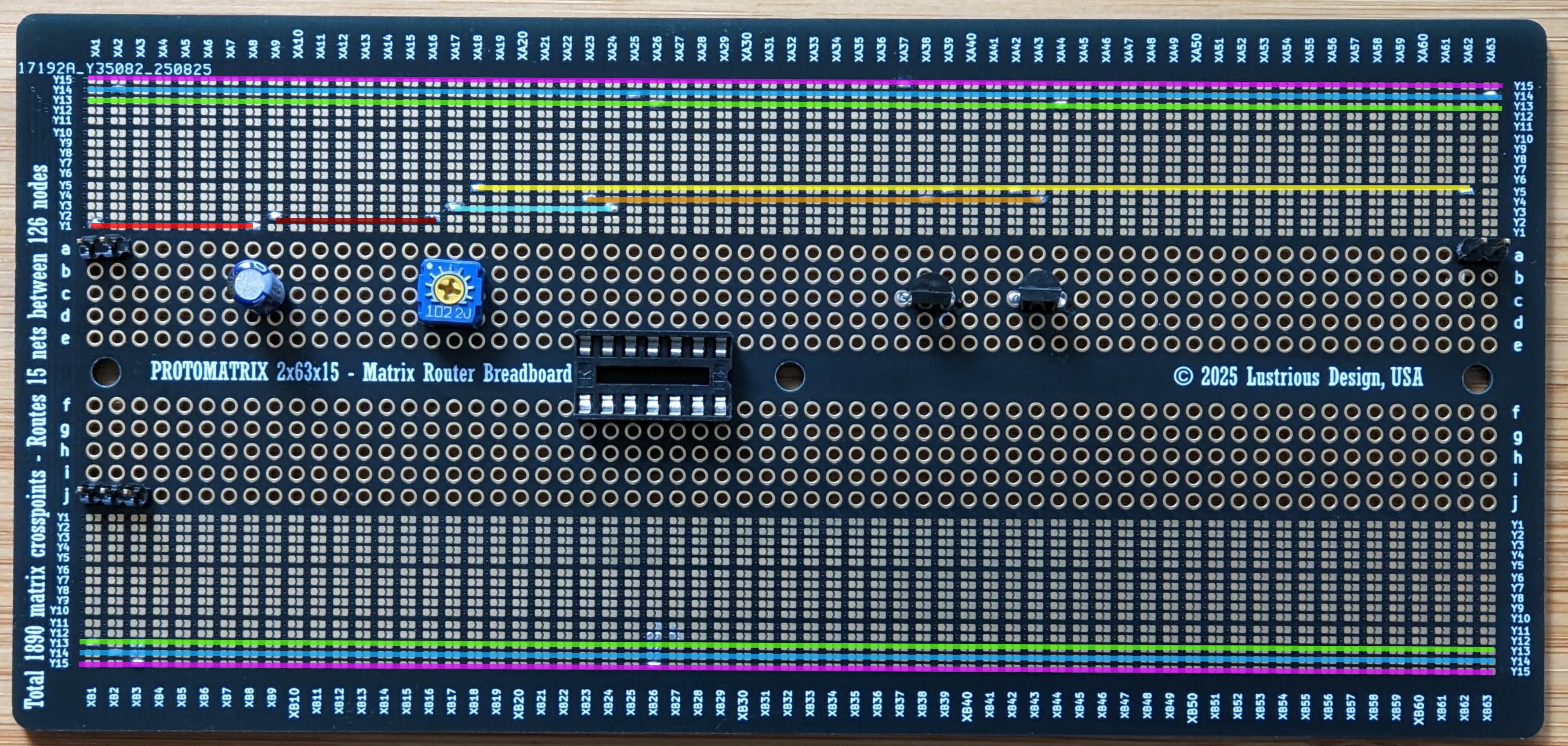
The matrix breadboard is pretty intuitive to use. Each NET in a circuit is just a line running across horizontally. The rows with same Y numbers are connected via hidden tracks running on the left. This may be easier to understand if you look at the layout (Protomatrix 2x80x30 Layout), see also links below.
Results
The circuit worked, but was a bit quiet due to small transistors. There was no noticeable distortion at lower volumes. At higher volumes transistors would drop into saturation with my 4 Ohm speaker and start clipping. I think the greatest weak point of the board are vias, since all connections are made through them, but they should be able to handle about 1 A. This should be enough for a small speaker. Having so many vias on the board ensures board houses hate you and so you get your money's worth!
Links
KiCAD Layouts & Layout Scripts
Discussions
Become a Hackaday.io Member
Create an account to leave a comment. Already have an account? Log In.