-
Home stretch
06/01/2017 at 11:37 • 0 commentsWe changed the code another time because something was not working. We did a time lapse to show you the final result. Check the video on our Twitter (@BrailleClock) !
-
Week 11
06/01/2017 at 11:34 • 0 commentsHome stretch, preparing the presentation for the CRI
![]()
-
10th week
05/26/2017 at 15:12 • 0 commentsHEY GUYS
All instructions were added to the page, you can now reproduce it if you want to !
-
9th week
05/26/2017 at 15:11 • 0 comments9th week :
LAST WEEK
HOPEFULLY WE FINALLY MAKE THE CODE WORK ! IT WORKS GUYS!!!
Now, we just have to fix everything in the box and organize it so it doesn't move and to have something solid that won't break just by taking it in your hands.
-
8th week
05/26/2017 at 15:10 • 0 comments8th week :
Coding
That week, we tried to make them turn one after the other but with a delay between each turn. We had an issue with the fonction "delay" which didn't work alone. Finally, we put it in a condition "if" and suddenly it worked.
Box
Today we did a plan for our box on a website in order to cut the sides in a medium board. Actually, at the beginning we wanted to print it entirely with the 3D printer. However, because of an issue with the time and the others classmates who also needed the printer, we came with this decision to make it on ourselves with our little hands. So we measured and estimated some measures for the box. Then we put those measures on the website.
After having upload the plan we had on the website, we had to open it on Adobe Illustrator CS6 then register the plan as a ".ai " file. After that, we opened it on a CoreIDRAW Essentials X6 and added some holes to the original plan (on the right side of the box) : a big hole to let the user touch the wheels , an other hole for the micro-usb cable to fit into the port on the Arduino. We also dit another hole with a drill above the last one (it is not on the plan) for the alimentation cable.
Look how the result is precise there !
P.S : You can already find the plan on our Hackaday files !!
-
7th week
05/19/2017 at 13:47 • 0 comments7th week :
First of all, we tried to make the 4 motors turn at the same time to see if it worked . We were able to do it. Then, the aim was to make them work but one after the other. There was some trouble because, we could make 2 turn at the same time but the third one didn't want to turn. But we finally managed to do it .
-
6th week : Mistakes correction + coding and printing
04/28/2017 at 13:06 • 0 commentsPrinting
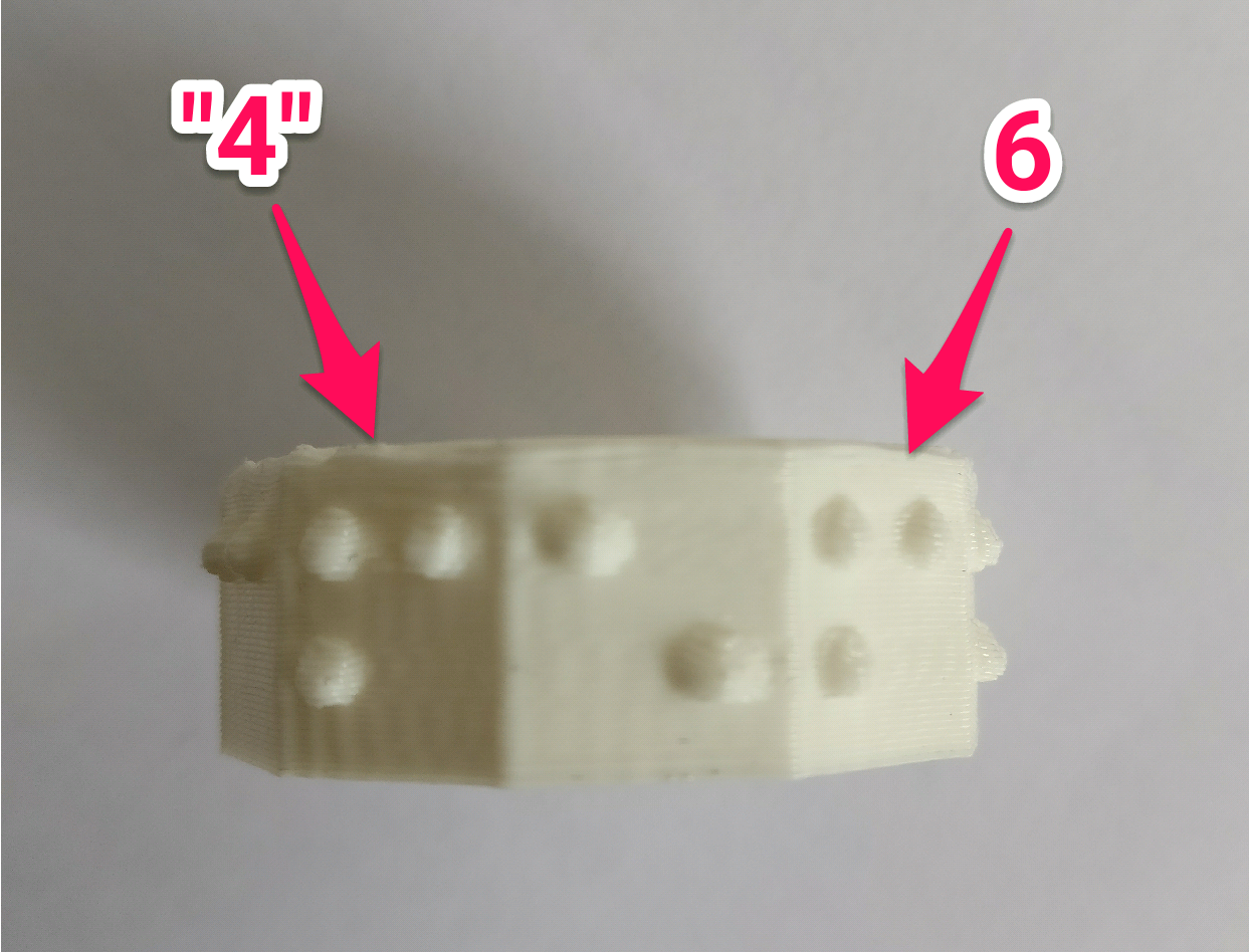
This week, we realized that there was a mistake on our wheels. The 4 was upside down (as you can see on the picture below) and was exactly like the 6.
![]()
So we had to re-print it and it took some time. Then we continue printing a second wheel. You can already find our wheels' files on Hackaday if you want to print them on yourselves at home.
Coding
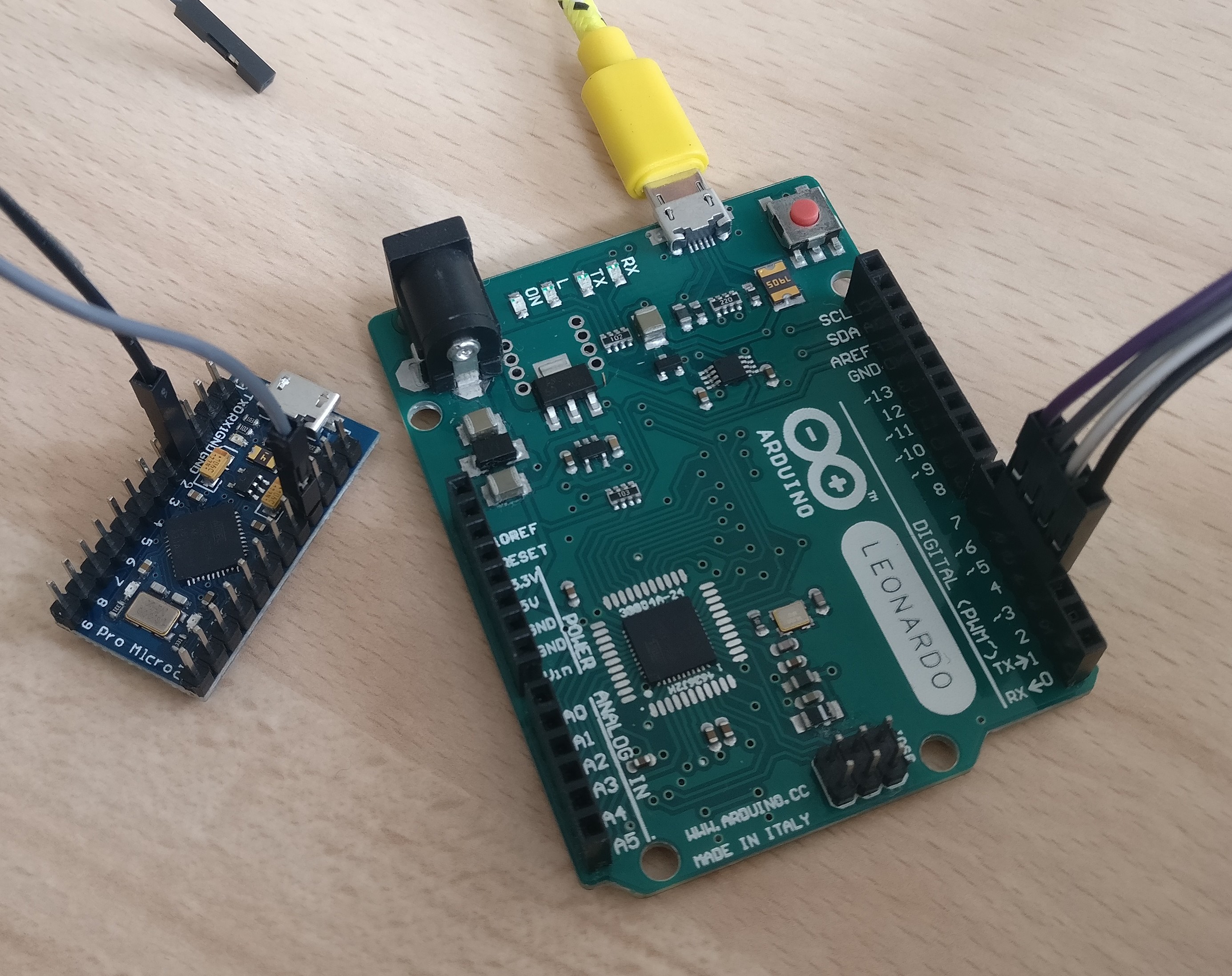
Here was also a mistake . We realized that the nano arduino didn't have enough pins to plug the 4 shields (each shield is related to 1 motor). So we had to take an Arduino Leonardo which is bigger.
![]()
And then we kept going with the code!
-
5th week
04/07/2017 at 14:04 • 0 commentsToday the fablab received motors ... but the wrong ones. Indeed, they received the continuous servo motors we wanted to order at the beginning but the stepper motors we ordered last week aren't there yet.
So, for the moment you can discover how our prototype will work :
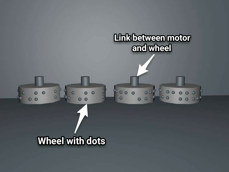
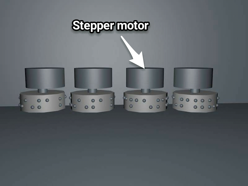
First of all, you can see bellow our wheel with the dots. There are only 4 dots by number because braille numbers are only code with the 1 to 4 dots. The wheels here are attached to a tip which is the link between the wheel and the stepper motor.
![]()
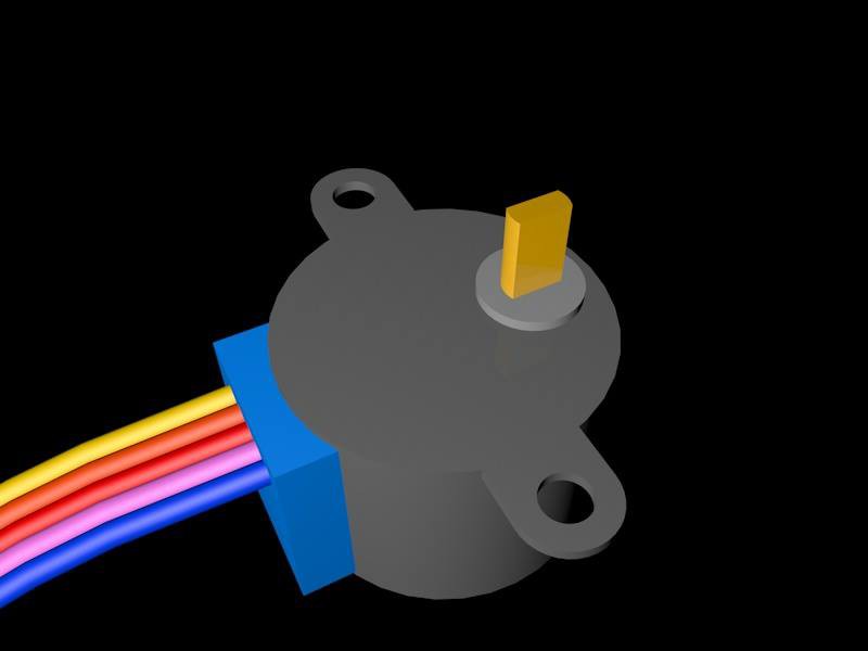
Then all of this will be attached to the stepper motor. The stepper motor, as its name shows, will make the will turn step by step, which is exactly what we need to make a clock. We managed to find one stepper motor and measured it to take its dimensions and modelize it so we could finally launch the wheels printing.
![]()
![]()
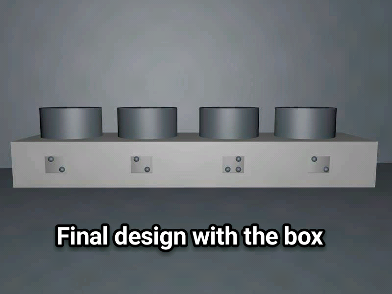
Stepper motor Finally, here is the final model with the box. The user will be able to read each number to have the time by putting his finger on the holes and slide it . The hole dimensions are designed to prevent the user to turn the wheel by accident and then disrupt the clock.
![]()
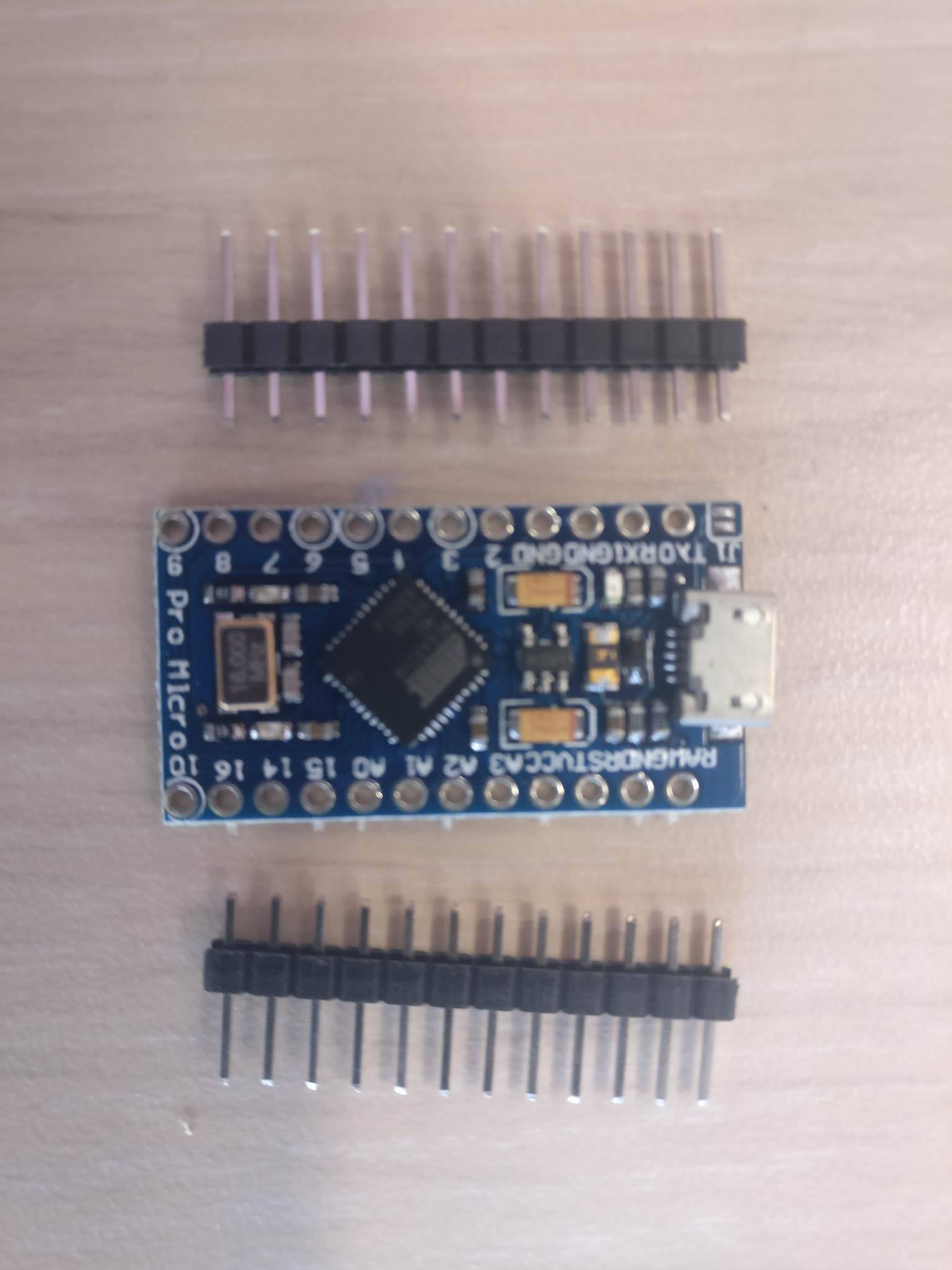
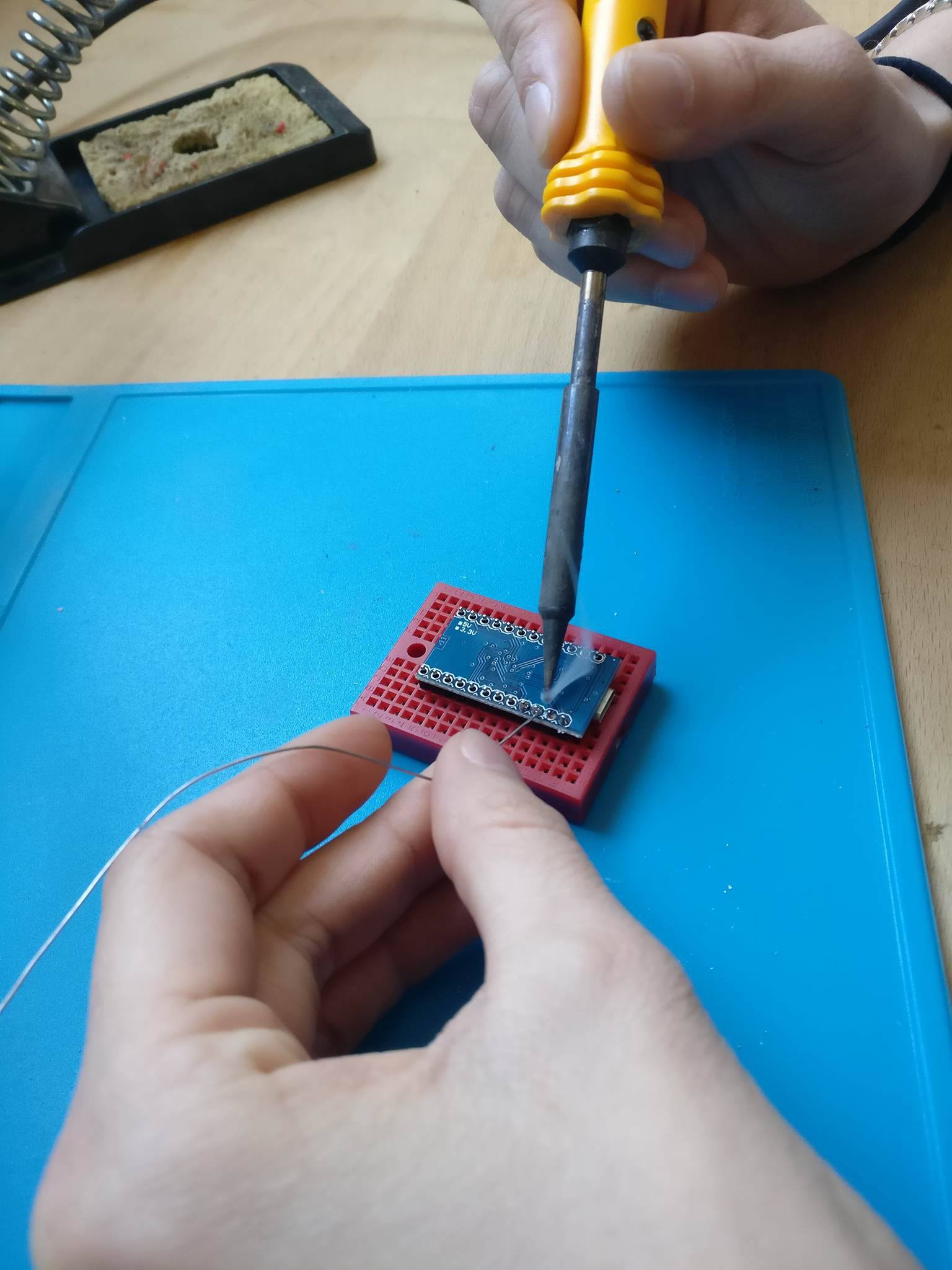
We also started coding. But before we soldered our arduino card ! Indeed, we received it like that (photograph on the left) then had to solder it on ourselves (photograph on the right).
![]()
![]()
With the code on Arduino, we were able to make the stepper motor turn as you can see on our twitter.
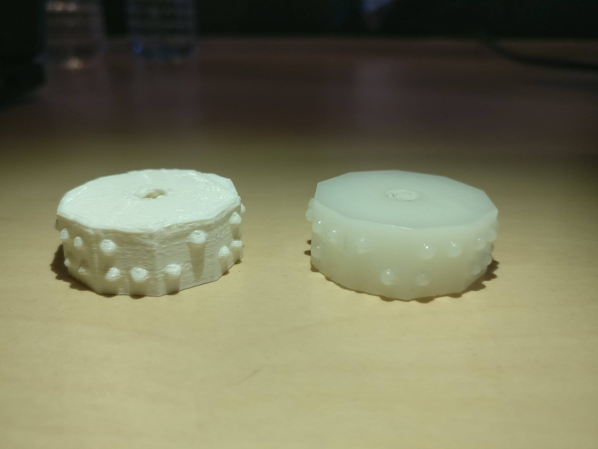
Finally, we printed our first wheels. The first one in ABS plastic (left) and the second one in resin (right).
![]()
Here it is ! This was a very productive week!
-
4th week : new shopping list
04/03/2017 at 20:09 • 0 commentsIt appears that the fablab we are working with did not order our servomotors. Anyway ! It seems like we'd ordered the wrong ones. With servomotors, we wouldn't be able to track the wheel's position. So instead we ordered stepper motors. Hopefully we will receive them in time for the 5th week .
-
3rd week : Design
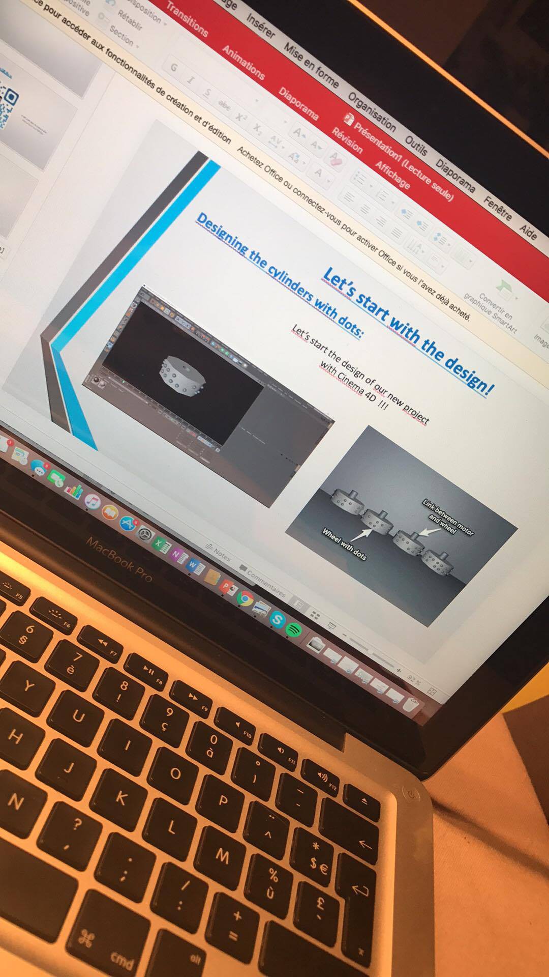
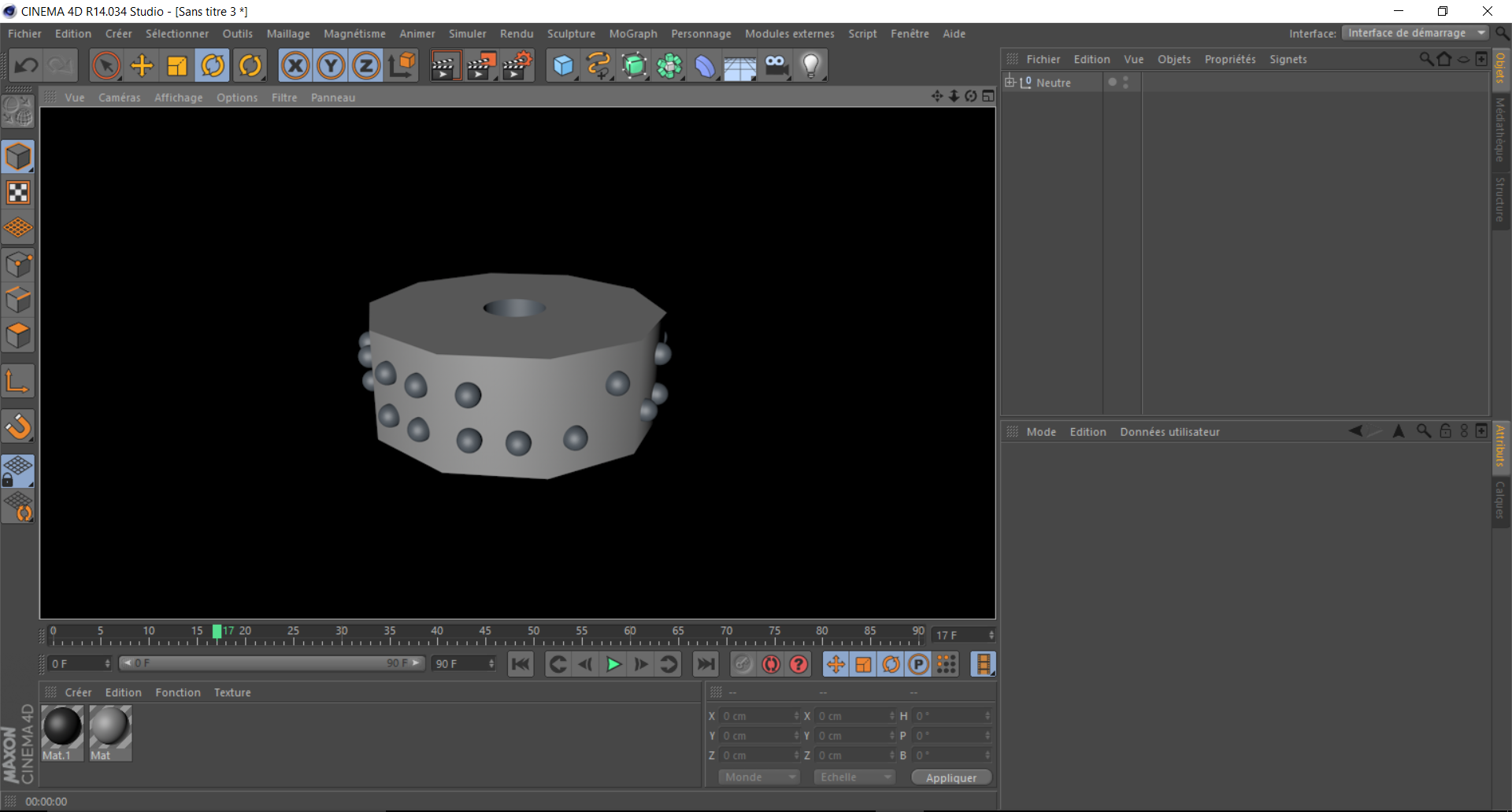
03/24/2017 at 15:06 • 0 commentsToday we are designing the cylinders with the dots in order to print them with the fablab's 3D printer. Each cylinder will have 10 sides and each side has up to 4 dots.
![]()
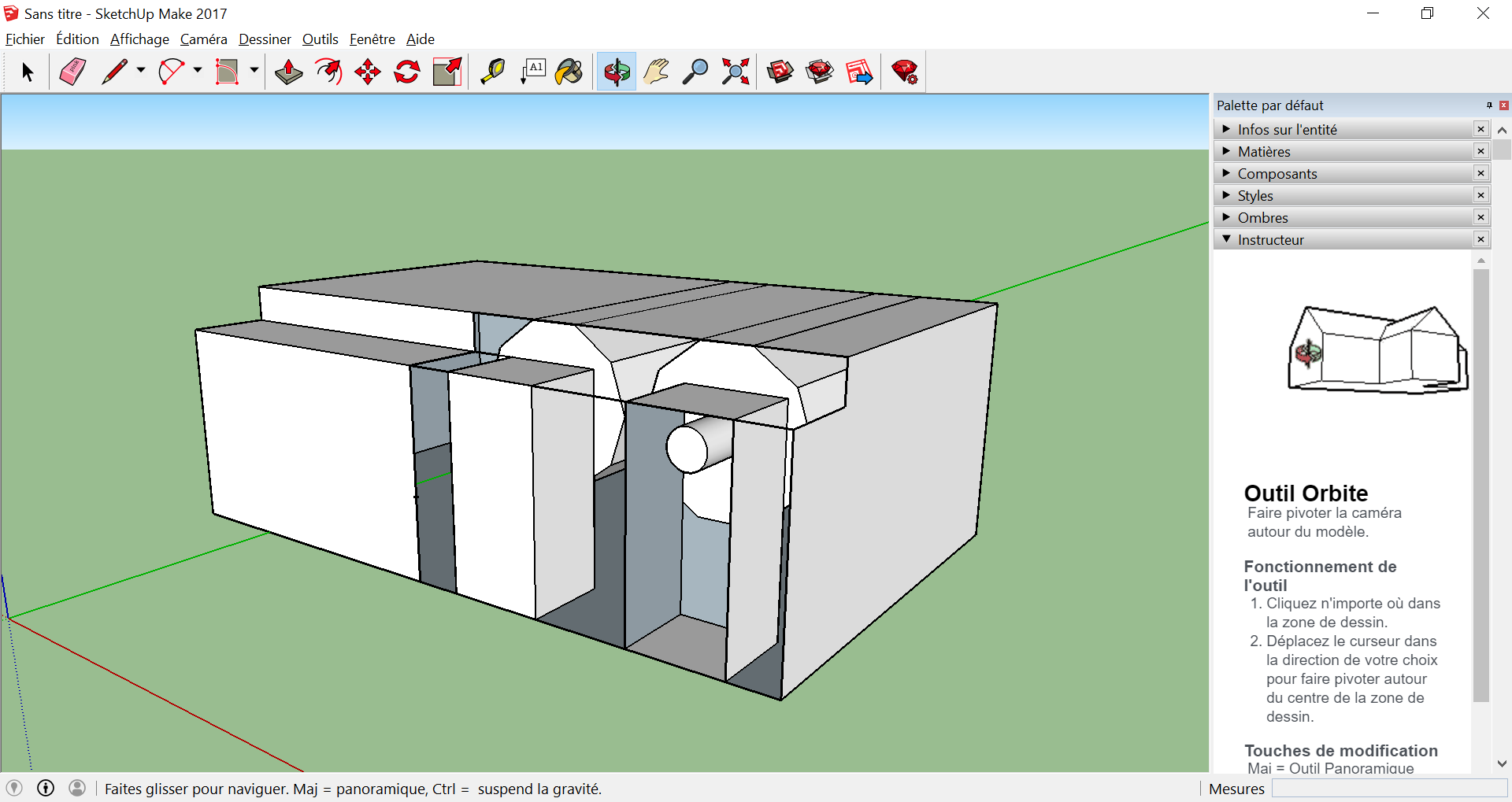
Then the second goal of the day was to design with Google Sketchup the box in which there will be the cylinders, the motors and the arduino card.
Braille Clock/Watch
Creating a "digital" braille clock/watch (for blind people obviously).
 Braille Clock