Close
0%
0%

typeCAD

programmatically create hardware

Public Chat
Similar projects worth following
177 views
TypeScript + KiCAD = typeCAD

- Write TypeScript code and build it into a KiCAD project
- Use all the normal software tools, but now for hardware
- Package your code into small packages
- Quickly combine known-working packages into larger projects

Instead of using the KiCAD schematic editor, you write code and build it into a KiCAD schematic.

typeCAD uses TypeScript. You don't need an extensive knowledge of TypeScript to get started.
If you're familiar with any programming language, you can pick up the basics of TypeScript pretty quickly.

KiCAD

The normal flow in KiCAD is:
1. Create a project and schematic
2. Add components
3. Make connections
4. Layout the board

typeCAD

typeCAD replaces steps 1-3. Instead of clicking and dragging to place components and make connections, TypeScript code is used.
This is how a schematic is created.

import { Schematic } from '@typecad/typecad';

let typecad = new Schematic('typecad');
typecad.create(); 

That code will create a KiCAD netlist named `typecad.net` which you can then import into a KiCAD PCB file. No schematic file is created because it's not needed.

Build
typeCAD projects have a build process. It takes the TypeScript code and turns it into a KiCAD project. The code you write and the typeCAD API simply run itself, resulting in the KiCAD project.

 
Workflow
The new layout becomes:
1. Create a typeCAD project
2. Edit the code to add components and make connections
3. Build it
4. Import the KiCAD netlist into KiCAD to layout the board

  • A visual git-diff for KiCAD

    typecad03/22/2025 at 05:43 0 comments

    KiCAD loves to put an * next to an open board file even if nothing important changed.

    Unlike other software tools, git isn't that useful to see file changes in KiCAD PCB files. That's why @typecad/typecad-gitdiff was written. Also to advance the march towards schematic-as-code with typeCAD.

    It will show the differences between two PCB files so you can be sure nothing important changed before you commit or send it to fab. 

    It can work with git and compares the last committed file versus the current file. 

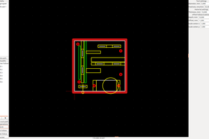
    It will create a render and highlight modifications in yellow and for each layer, it will show additions in green and deletions in red.

    Install

    Enter the following in a terminal.

    npm i -g @typecad/typecad-gitdiff

     It will install the package globally so it can be run as a regular binary file (assuming you have Node installed)

    Usage

    Once it's installed, you can run it like this:

    typecad-gitdiff <original.kicad_pcb> <modified.kicad_pcb>

    Or you can use it with git and compare the last committed file:

    git difftool <modified.kicad_pcb> --extcmd 'typecad-gitdiff'

     Just replace <modified.kicad_pcb> with the actual file to compare. git will extract the committed file for you and pass it along to typecad-gitdiff.

    After that, it will run, and an HTML file will open with all the changes to view. 

  • JLCPCB-Export

    typecad03/19/2025 at 15:25 0 comments

    Integrating software tools like git or various CI/CD methods is possible within typeCAD. 

    Running ERC on the code can be done with commands, DRC on the PCB is possible,  and with @typecad/jlcpcb-export all the required files to have JLCPCB assemble your board can be created. 

    The package could be integrated into a Github script, or it could be more locally used by creating a git hook. 

    The result is a convenient zip file with all the files formatted specifically for JLCPCB's assembly service. 

    You can read more about this on typeCAD's website

  • ngspice

    typecad03/19/2025 at 12:45 0 comments

    One of the benefits of schematic-as-code is it avoids the tediousness of drag-and-drop GUIs. The various spice simulations often require the same drag-and-drop steps and maybe even recreating the schematic. typeCAD lets you use your code with only very minor changes.

    Your code might look like this, conveniently a voltage divider circuit:

    import { Schematic } from "@typecad/typecad"
    import { Resistor } from '@typecad/passives/0603';
    
    let typecad = new Schematic('voltage_divider');
    let r1 = new Resistor({ value: '10kohm' });
    let r2 = new Resistor({ value: '10kohm' });
    
    typecad.named('vdiv').net(r1.pin(2), r2.pin(1));
    
    typecad.create(r1, r2);

    Import the package

     npm install @typecad/ngspice

    And add a few ngspice-related code changes.

    import { Schematic, Power } from "@typecad/typecad"
    import { Resistor } from '@typecad/passives/0603';
    import { ngspiceSimulator } from '@typecad/ngspice';
    
    let typecad = new Schematic('voltage_divider');
    let r1 = new Resistor({ value: '10kohm', simulation: { include: true } }); 
    let r2 = new Resistor({ value: '10kohm', simulation: { include: true } }); 
    let vin = new Power({ power: r1.pin(1), gnd: r2.pin(2), voltage: 3.3 }); 
    let ngspice = new ngspiceSimulator(typecad, vin);
    
    typecad.named('vdiv').net(r1.pin(2), r2.pin(1));
    
    typecad.create(r1, r2);
    
    ngspice.op();

    That will output this giving you information about all the named nets and components:

    🌶️ Running ngspice
    ┌────────────────────┬───────────────┬────────────────────┐
    │ VariableTypeValue              │
    ├────────────────────┼───────────────┼────────────────────┤
    │ r1:powerpower         │ 2.7225 mW          │
    ├────────────────────┼───────────────┼────────────────────┤
    │ v(in)              │ voltage       │ 3.3000 V           │
    ├────────────────────┼───────────────┼────────────────────┤
    │ i(r1)              │ current       │ 1.6500 mA          │
    ├────────────────────┼───────────────┼────────────────────┤
    │ i(r2)              │ current       │ 1.6500 mA          │
    ├────────────────────┼───────────────┼────────────────────┤
    │ r2:powerpower         │ 2.7225 mW          │
    ├────────────────────┼───────────────┼────────────────────┤
    │ i(v1)              │ current-1.6500 mA         │
    ├────────────────────┼───────────────┼────────────────────┤
    │ v(vdiv)            │ voltage       │ 1.6500 V           │
    └────────────────────┴───────────────┴────────────────────┘
    

    You can read about this in more detail on the typecad.net website

  • Schematic-as-code

    typecad03/18/2025 at 00:13 0 comments

    The first thing people might wonder is why

    The answer is:

    • why not?
    • some people might prefer it
    • GUI's are error-prone
    • AI knows TypeScript well, it doesn't know the first thing about creating schematics
    • reusing KiCAD projects is not a feature they are working toward
    • using git on a KiCAD schematic isn't that useful

    It won't be for everyone and that's ok.

    Schematic-as-code

    What does schematic-as-code mean exactly? 

    It means writing code (TypeScript in this case) that when ran, outputs a KiCAD netlist. Import the netlist into the PCB Editor, and go from there. 

View all 4 project logs

Enjoy this project?

Share

Discussions

Rich text editor

Similar Projects

Does this project spark your interest?

Become a member to follow this project and never miss any updates