
My objectives for this project are as follows:
- Create the smallest blinky LED circuit - smaller than the current record holder (3.2 x 2.5 mm by mikeselectricstuff)
- The circuit should be soldered onto a PCB. No creative dead bug soldering or stacked components allowed! (self-imposed rule). I want the techniques I develop to be applicable in other projects.
- Learn something. This is mostly meant to be an exercise for myself to help develop my fabrication skills and hopefully lead to something that's actually useful.
---Design #1---

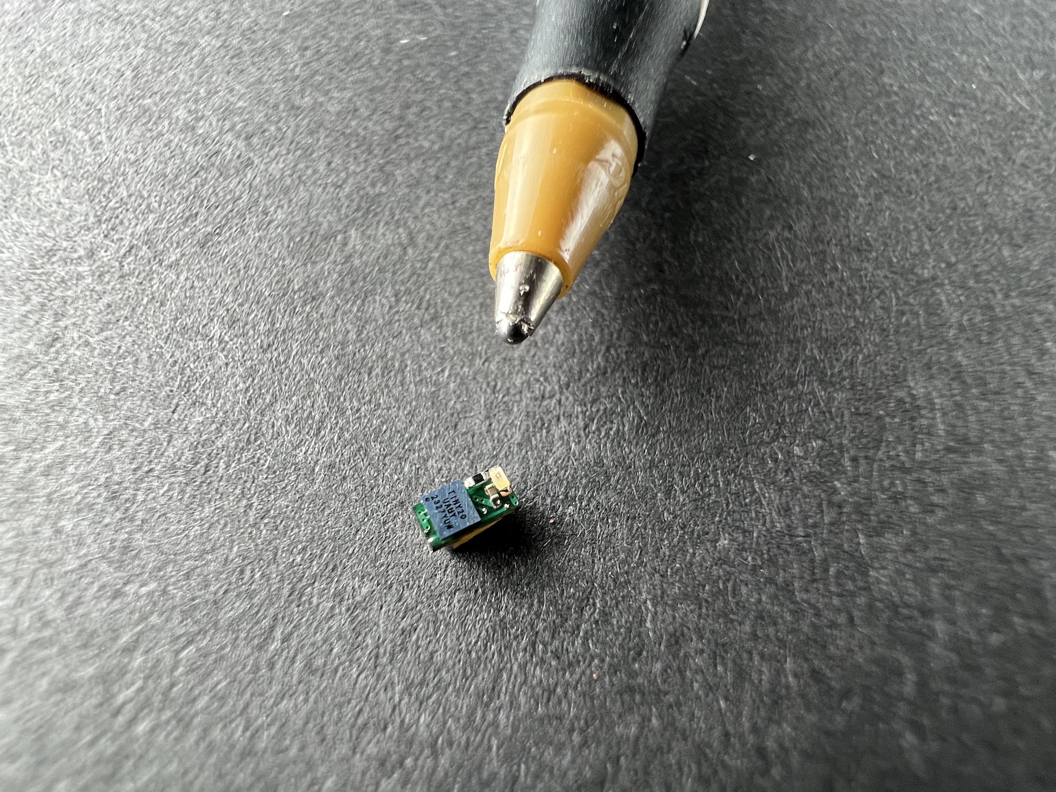
I'm using an attiny20 microcontroller in the WLCSP package, which has a footprint of 1.55 x 1.4 mm. At the time of writing, this is currently the smallest available microcontroller (TI XMSM0C1104S8YCJR is still in preproduction)
A red 0201-size LED is connected in series to a 2kOhm resistor 0201 size
A 1uF 01005 decoupling capacitor is connected to VCC.
Power comes from a 220uF tantalum capacitor with a size of 3.2 x 1.6 x 1.0 mm. This dictates the size of the PCB. The PCB laminate thickness is roughly 0.3mm
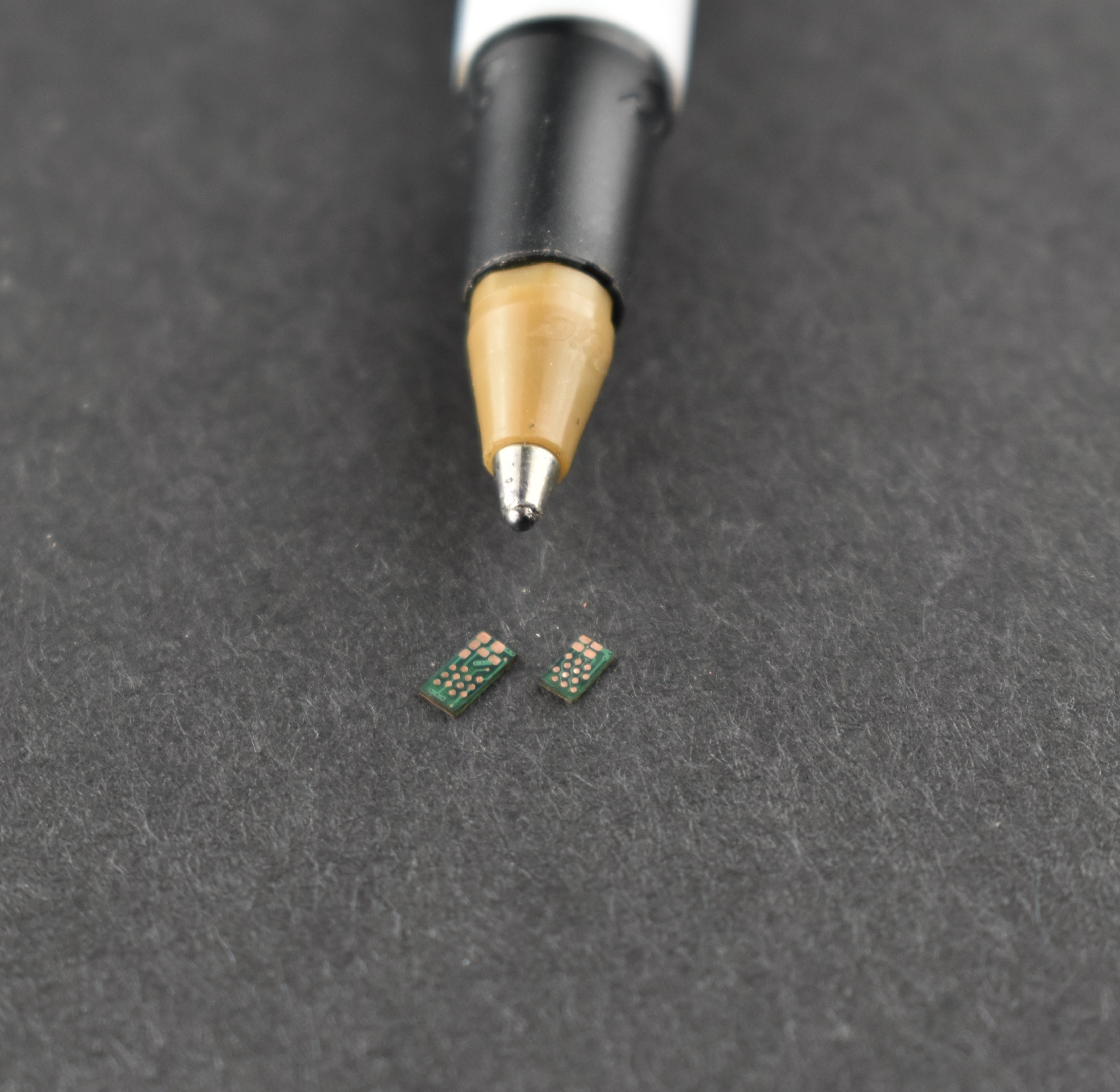
(Design #1 is the larger design, Design #2 is the smaller one)
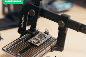
After fabricating the PCB, I populated the top side with components by applying a thin layer of flux to the microcontroller WLCSP pads and a few dabs of solder paste onto the pads for the other components. I used a hand held vacuum tool to place the components. The application of vacuum is controlled by a foot pedal. All of this work was performed under a stereomicroscope (Nikon SMZ1000 with 0.5X Plan Apo objective)
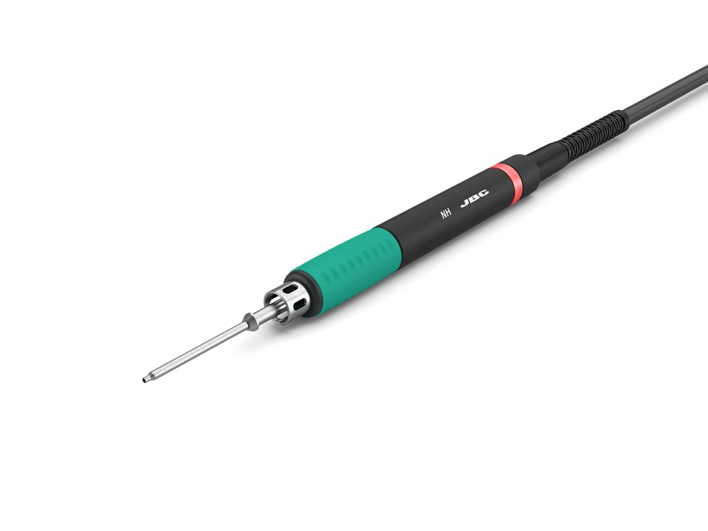
For reflow soldering, I initially placed the PCB on a hotplate/stirrer and discovered the magnetic field caused the components to move around and stick straight up, so I decided to use a hot air tool to reflow the board. I used very low air flow to prevent the components from being blown off.
Programming the board was perhaps the trickiest part of the project. I created probe points by removing solder mask at the ends of some of the traces. My intent was to use pogo pins to touch the pads, but the smallest pogo pins I could find on Amazon were too big. Instead, I used 38 AWG wire and soldered to the points on the PCB.
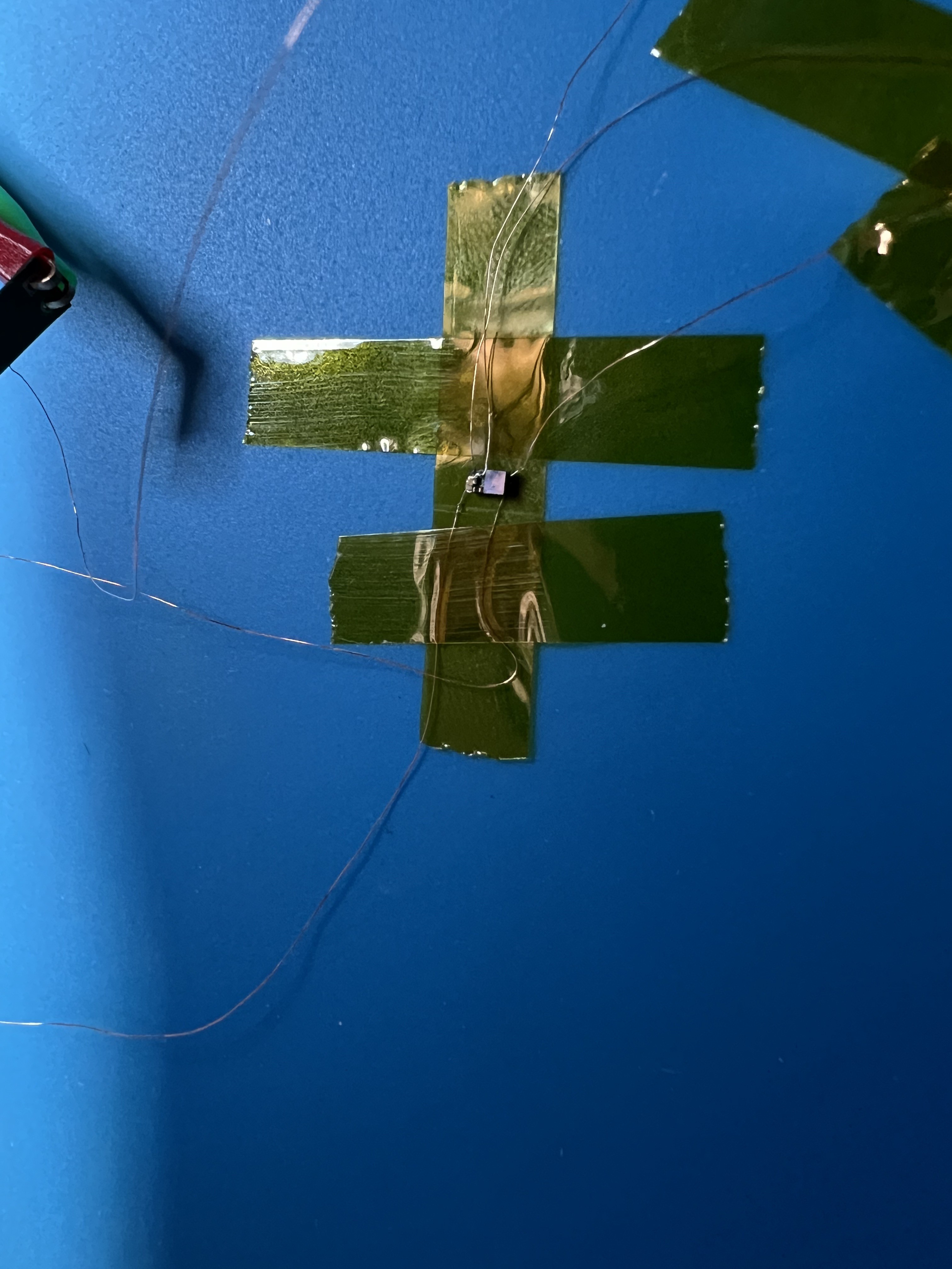
The programmer initially failed to recognize the chip, so I reworked the wire connections by adding more solder paste to the test pads and reflowing it into a big ball using a micro hot air tool. After getting the big ball of solder on the pad, I applied some flux to the solder and the wire, used the micro hot air tool to reflow the solder ball, and stuck the wire into the molten solder. This worked much better than using a soldering iron to make the connection.
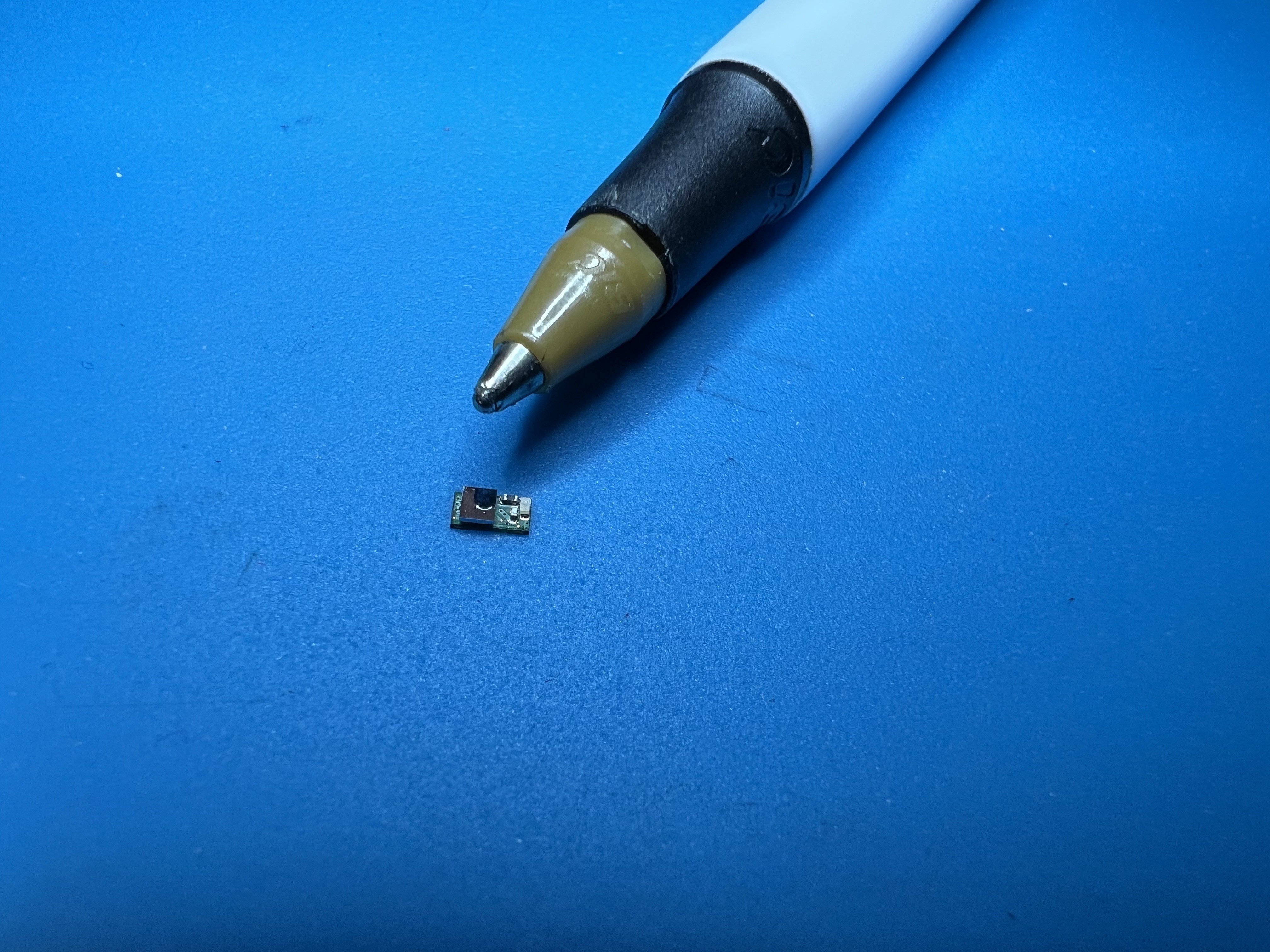
After programming, the tantalum capacitor was soldered on and the device was complete.
Applying 3.6V to the capacitor charges it up and it blinks at 1Hz for about 20 to 25 seconds
---Design #2---

After ordering the parts for design #1, I realized that my parametric search on Mouser missed some smaller parts I could have used. I found a smaller 220uF tantalum cap and an 01005-size red LED to use in my next version. I also decided to eliminate the decoupling cap since the microcontroller is only running at 128kHz. With these changes, the footprint of the PCB has been reduced to 2.4 x 1.45 mm.
With less real estate in this design, I used some of the component pads as programming connection points, so I will solder just the microcontroller on the PCB, program it, and then populate the rest of the board.


 SolderJaw
 Erik Bosman
 Chromico
 Sanjit Sarda
Slick work! Impressive you manufactured that PCB yourself, with soldermask and gold plating no less??
That new TI part got a bunch of hype - and it's cool as heck - but it might also be worth looking at the GreenPak devices from Renesas? This guy is 1.2mm^2 (vs 1.38mm^2 for the TI part), and it's OTP - so you could program it off-board before SMT. It's got an internal RC oscillator and some counters so I'm 99% sure you could make it go blink.
https://www.renesas.com/en/document/dst/slg46108-datasheet?r=1563661