 Fangzheng Liu
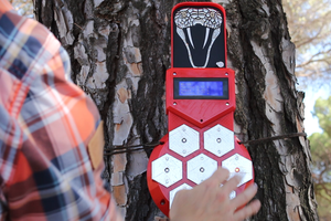
(Circle pads are analog pins and square pads are digital pins)
Here is how I implement this:
1. Analog pins
For analog pins (pins connected with internal ADC), The touchpad that connects with an analog pin forms a capacitor with the ground pour. First, the analog pin outputs a very short pulse to charge the capacitor. Then the pin turns to analog input, which has big input resistance, and the capacitor discharges slowly through this big resistance. When your finger touches the pads, the capacitance will be bigger which causes a slower discharging process (discharge slower), as shown in the image.
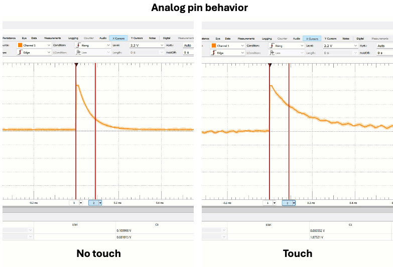
By taking a measurement at a fixed time point after the pulse, we can detect the change in discharge and detect the touch. When you touch it, the reading will be higher than when the pad is empty.
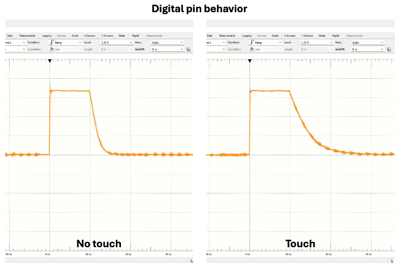
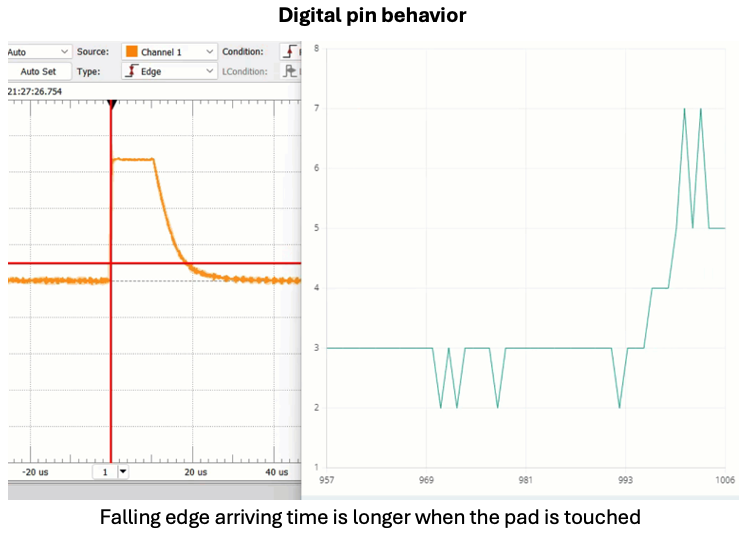
2. Digital pins
The mechanism for digital pins is similar. When touching the pad, the capacitance increases, and the discharging process changes. However, digital pins are not connected with the internal ADC therefore can not measure this change by sampling the voltage at a fixed moment. The approach I'm using for digital pins is: when touching the pad, the discharge gets slower, therefore the falling edge arrives later. So I record the timestamp when the pulse outputs, and set the digital IO to input and attach to an interruption with it which is triggered by a falling edge. The interruption routine records the timestamp and calculates the time difference between the trigger time and pulse output time. The time difference with a finger touch is longer than the one without (although it's only a few microseconds, but already enough to capture). As shown in the images, when the pad is touched, the falling edge triggering time is longer. It will be better to add a filter to the data.
Platform:
- Firmware: Platformio + VScode (Arduino framework)
- Hardware: XIAO RP2040 + a milled PCB.
 Estudio Roble
 Arduino KIT
 Hulk
Hulk